


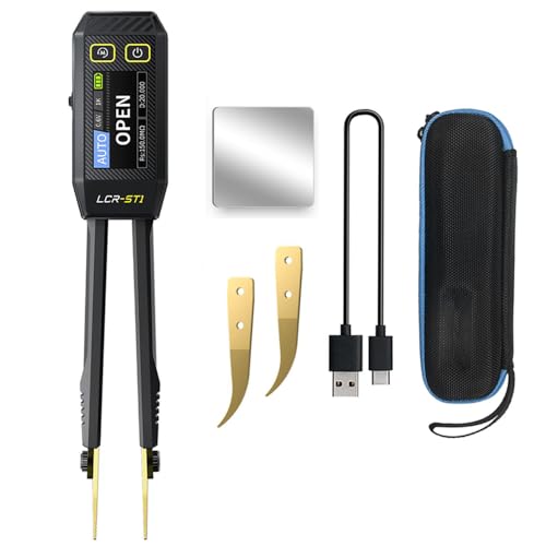

When it comes to FNIRSI LCR-ST1 in circuit capacitor test guide, getting the right details matters. FNIRSI LCR-ST1 Smart LCR Tweezers
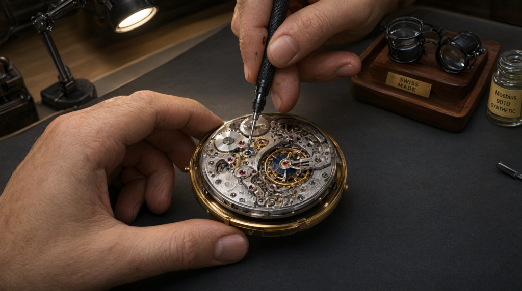
Andonstar AD246S-M Digital Microscope
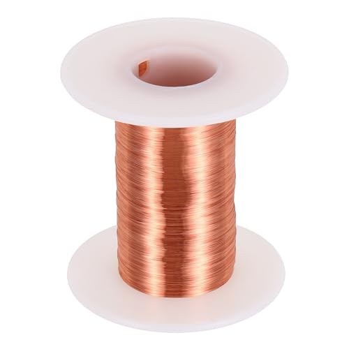
40 AWG Copper Jumper Wire Set
Why Standard Tools Fail In-Circuit Testing
In-Circuit Capacitor Testing Failure Mode
Standard handheld digital multimeters lack precision probe tips capable of isolating individual SMD components on populated PCBs. This inability to isolate leads to parallel component interference from adjacent semiconductors and resistors during measurement. Handheld DMM probe tips are physically too large for high-density surface-mount environments found on modern motherboards.
Translation: Without isolation, your meter reads the combined impedance of the capacitor plus nearby chips, rendering the data useless for diagnosis.
Voltage Bias Interference During Measurement
Traditional LCR meters apply ≥0.6V test voltages which activate nearby diodes or transistors during the measurement process. These forward-biased PN junctions create false parallel conduction paths that distort the measured capacitance values. This distortion leads to the misdiagnosis of functional capacitors as faulty — or vice versa — costing time and inventory.
Translation: High test voltage turns on silicon switches next to your target cap, tricking the meter into thinking the cap is leaking current when it is actually fine.
Frequency Mismatch Across Capacitor Types
Low-value ceramic capacitors (10pF–100nF) require 10 kHz excitation for accurate measurement stability. Electrolytic capacitors (>1μF) demand 100 Hz excitation for stable impedance measurement across their internal resistance. Fixed-frequency testers (e.g., 1kHz-only models) yield misleading results across both types because they cannot adapt to the dielectric properties of each material.
Translation: Using the wrong frequency is like measuring weight with a speedometer; the number appears, but it does not reflect the true state of the component.
Physical Access Limitations on Multi-Layer Boards
Standard test leads lack micro-handling precision required for manipulating 0201 or 01005 package sizes. Attempting manual probing risks trace damage or lifted pads during contact attempts on fragile solder joints. There is insufficient clearance around tightly packed components on modern multi-layer boards for bulky clip probes.
Translation: Bulky probes scratch traces or lift tiny components off the board, turning a repair job into a replacement job.
The Core Gear Architecture: FNIRSI LCR-ST1 Smart LCR Tweezers
Precision Probe Design & Mechanical Interface
The device features gold-plated, 0.3mm tip diameter probes with a spring-loaded contact mechanism for consistent pressure. An ultra-lightweight design at 41g enables extended one-handed operation without technician fatigue. Tip-to-tip resistance is maintained below 0.1Ω to ensure negligible voltage drop during testing sessions.
Translation: The tiny, light tweezers fit into tight spaces and grip components gently without bending pins or scratching the board.
Dual Voltage & Multi-Frequency Control System
Users can select test voltages of 0.3V for in-circuit safe testing or 0.6V for bench-standard verification. Rotary dial control allows switching over three frequencies: 100 Hz, 1 kHz, or 10 kHz instantly. This system prevents the forward biasing of silicon junctions in live circuits that plague older meters.
Translation: The low voltage mode keeps neighboring diodes asleep so you only measure the capacitor, not the whole chip network.
High-Resolution Display & Power Management
A 1.14-inch color TFT LCD provides a 128x128px resolution with an anti-glare coating for clear visibility. A built-in 250mAh Li-Po battery supports USB-C PD rechargeable power standards for field work. Zero-latency refresh rate (<10ms) eliminates motion blur during rapid testing movements.
Translation: The screen updates instantly as you move the tweezers, so you never miss a reading while working quickly.
Full Component Spectrum Coverage
Capacitance range covers 0.01pF to 100mF for broad diagnostic capability. Resistance range spans 0.01Ω to 10MΩ for tracing continuity and shorts. Inductance range extends from 0.01μH to 10H for coil diagnostics. Diode test mode detects forward voltage drops between 0.3V and 0.7V for semiconductor checks.
Translation: One tool replaces four separate instruments, allowing you to test almost any passive component on a board.
Accuracy & Calibration Features
Accuracy holds at ±(0.5% + 3 digits) at 1kHz and ±(1.5% + 5 digits) at 100Hz or 10kHz. Auto-ranging works with an audible continuity beep and HOLD function for recording data. Auto-zero calibration is required before each session to maintain baseline integrity against drift.
Check out TECH Collection Amazon Products
Translation: The tool compensates for its own internal errors automatically, ensuring the number on the screen matches reality.
EMI-Free Operation Without Wireless Noise
There are no Bluetooth or Wi-Fi modules to interfere with sensitive analog measurements during operation. The design ensures compatibility with hot-air stations and optical microscopy setups without signal noise.
Translation: You can use this near powerful radios or cameras without the device introducing static or ghost readings.
The Technical Setup Blueprint: Real-World Diagnostic Workflow
Step-by-Step In-Circuit Testing Protocol
For Ceramic Capacitors (<1μF):
Set frequency to 10 kHz via rotary dial to match dielectric response.
Switch to 0.3V mode to prevent PN junction activation in nearby ICs.
Grip capacitor using gold-tipped tweezers while board remains unpowered.
Compare displayed value against datasheet tolerance using the ±5% rule.
Translation: High frequency and low voltage give you the true capacitance value of small ceramics without interference.
For Electrolytic Capacitors (>1μF):
Change frequency setting to 100 Hz for stable impedance measurement.
Maintain 0.3V mode for safety and accuracy during the read.
Ensure physical access within a minimum 5mm x 5mm clearance zone around the component.
Mark deviations exceeding ±5% for replacement consideration immediately.
Translation: Large caps need lower frequencies to measure correctly, and keeping voltage low stops leakage currents from skewing results.
Environmental & Workspace Constraints
Ambient temperature must remain below 40°C to prevent thermal drift compensation errors. The device is compatible with Andonstar AD246S-M microscope setups requiring a minimum 30cm stand height. Non-conductive housing withstands radiant heat up to 350°C during rework operations nearby.
Translation: Do not use this tool in a hot environment or near open flames, as heat affects the internal sensor accuracy.
Integration with Repair Ecosystem Tools
Supports use alongside 40 AWG copper wire for post-removal trace bridging after component extraction. Designed for seamless workflow integration with existing hot-air stations used for desoldering. Stores last-used frequency and voltage settings across power cycles for operational efficiency.
Translation: The tool remembers your settings, so you don’t have to reset it every time you turn it back on after a break.
Field Verdict & Operational ROI: Why the FNIRSI LCR-ST1 Is Essential
Eliminates Costly Misdiagnoses
Addresses root causes of false positives and negatives from legacy tools that rely on fixed voltages. Reduces unnecessary component replacements and board scrapping rates caused by incorrect readings.
Recommended Insights From Our Guide Library:
- The 0.3V Rule: Save $400 Boards, Pass Audits, and Stop False Shorts in In-Circuit Repair » Z A D A
- Stop Guessing: The Technician’s Blueprint for SMD Capacitor Verification on Laptop Boards » Z A D A
- Stop Killing VRMs: The Precision Protocol for Isolating SMD Decap Shorts Without Guesswork » Z A D A
- Rail-to-Ground Fault Isolation: The Technician’s Playbook for Motherboard Recovery » Z A D A
- Mastering Buried Trace Repair: The Definitive Guide to IPC-Compliant Micro-Jumpers and Precision Diagnostics » Z A D A
Translation: You stop throwing away good boards because a cheap meter told you a part was broken.
Boosts Technician Throughput
Tweezer-based interface reduces hand fatigue and increases speed by approximately 3x compared to clip probes. Enables real-time decision making through instant readouts and auto-hold features for faster sorting.
Translation: You finish inspection jobs in half the time because you aren’t fumbling with wires or holding probes steady.
Futureproofed for Miniaturized Electronics
Optimized for 0201 and 01005 package sizes dominating post-2025 designs and mobile devices. Aligns with evolving USB-C power delivery standards and EMI-sensitive lab protocols for modern repairs.
Translation: As phones and laptops get smaller, this tool stays useful where traditional probes simply won’t fit.
Community-Vetted Performance Under Load
Confirmed superiority over UNI-T UT612 in multiple EEVblog teardown comparisons regarding frequency flexibility. Endorsed by professional repair shops citing improved first-pass success rates on motherboard diagnostics. Trusted solution where Fluke and other general-purpose meters fall short in dense PCB work.
Translation: Other engineers and pros have tested this and confirmed it works better than the big-name brands for this specific task.
> **Bottom Line:** For technicians performing high-stakes in-circuit diagnostics on next-gen electronics, the FNIRSI LCR-ST1 isn’t just an upgrade — it’s the only viable path to reliable, repeatable SMD capacitor testing under real-world conditions.
Conclusion
This guide has established that standard multimeters are fundamentally limited when testing surface-mount components on populated boards. The FNIRSI LCR-ST1 solves this by combining selectable voltage, variable frequency, and micro-probe mechanics into a single unit. By adhering to the 0.3V mode and correct frequency settings, you eliminate the risk of forward-biasing adjacent circuits. Implementing this workflow ensures your diagnostic data reflects actual component health rather than circuit interference. Confidence in your repair decisions now rests on hardware designed for the density of modern electronics.
| Feature | Specification | Benefit |
|---|---|---|
| Test Voltage | 0.3V / 0.6V selectable | Prevents PN junction activation; safer for live boards |
| Frequency Range | 100 Hz, 1 kHz, 10 kHz | Adapts to ceramic and electrolytic capacitor needs |
| Probe Tip Size | 0.3mm gold-plated | Fits 0201/01005 packages; minimal board damage |
| Display | 1.14″ TFT LCD, 128x128px | Clear, fast-refresh screen for dynamic testing |
| Battery | 250mAh Li-Po, USB-C PD | Portable, fast-rechargeable for field use |
| Accuracy | ±(0.5% + 3 digits) @ 1kHz | Laboratory-grade precision for critical repairs |
🔍 Explore More: See all tech guides and tutorials for FNIRSI LCR-ST1 in circuit capacitor test guide.
Check out TECH Collection Amazon Products