


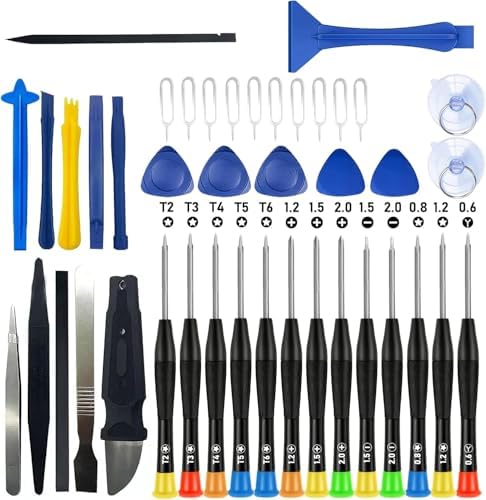



When it comes to how to test SMD capacitors on laptop motherboard using FNIRSI LCR-ST1, getting the right details matters. FNIRSI LCR-ST1 Smart LCR Tweezers
Andonstar AD246S-M Digital HDMI Microscope
40 AWG Micro-Thin Jumper Wire
How to Test SMD Capacitors on a Laptop Motherboard Using the FNIRSI LCR-ST1: A Technician’s Diagnostic Blueprint
When a laptop motherboard refuses to power on, drops a rail, or reboots under load, the culprit is often a single failed SMD capacitor hiding in a forest of 0201, 0402, or 0603 packages. Standard handheld multimeters cannot reliably measure these parts in-circuit, and guessing usually leads to unnecessary component swaps or worse—collateral damage.
This guide shows you how to test SMD capacitors on a laptop motherboard using the FNIRSI LCR-ST1 smart LCR tweezers, from failure-mode recognition through definitive out-of-circuit verification.
You will learn the four capacitor failure signatures that matter, why selectable test frequency and 0.3 V in-circuit mode are non-negotiable, the exact hardware stack that makes the job repeatable, and a step-by-step diagnostic workflow you can run on any laptop board.
The Technical Reality / The Failure Point
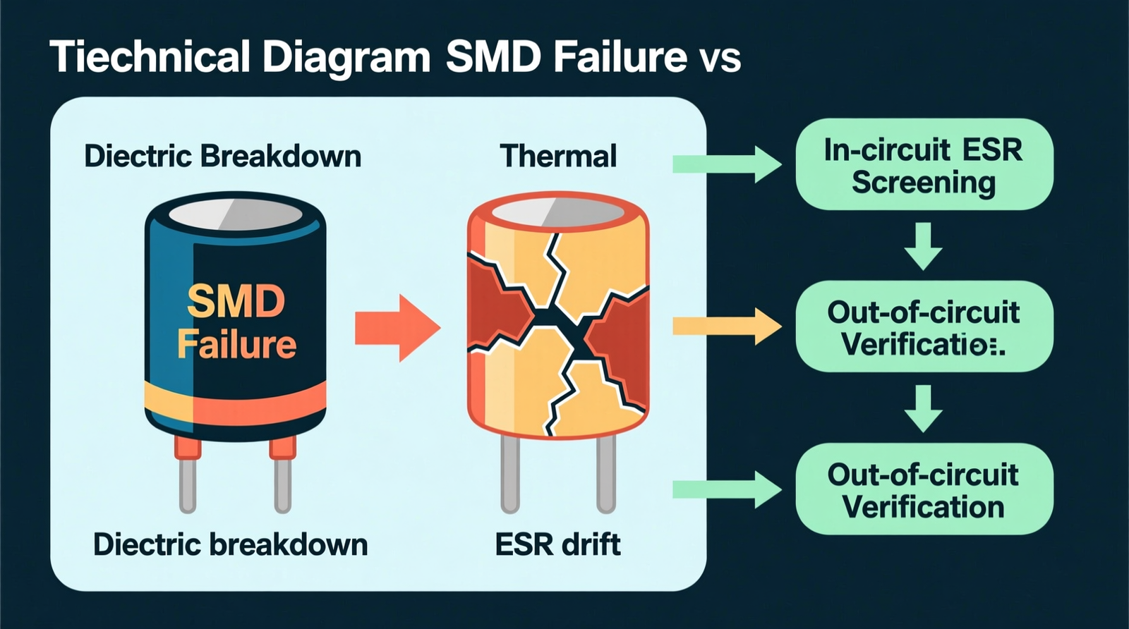
Shorted MLCCs: Dielectric Breakdown and Power-Rail Collapse
A multilayer ceramic chip capacitor can fail when its internal dielectric breaks down, creating a low-resistance path between a power rail and ground.
The practical result is excessive current draw, a PMIC shutdown, or a no-boot condition where a shorted MLCC near the CPU or GPU VRM pulls the entire rail to ground and makes the system look completely dead.
Open-Circuit Capacitors: Thermal Cycling and Mechanical Fracture
Laptop motherboards flex, and repeated thermal cycling, drops, or chassis torque can crack the internal electrode layers of an SMD capacitor, severing the conductive path.
When that path severs, the capacitor no longer decouples the rail, resulting in rail instability, voltage ripple, and nearby ICs behaving erratically where the board may boot sometimes and crash others.
Capacitance Drift and ESR Rise in Electrolytic/Tantalum SMDs
Electrolytic and tantalum SMD capacitors degrade as their electrolyte dries or their oxide layer ages, causing capacitance to drop and equivalent series resistance to rise.
The rail loses its ability to filter noise, so you see voltage sag, ripple, and degraded decoupling performance even though the capacitor is not shorted or open.
Solder Fracture and Cold-Joint Intermittence
BGA-style motherboard flex does not just crack traces; it can fracture the solder joints at capacitor terminals, creating intermittent contact resistance.
The failure signature is intermittent contact where the laptop works on the bench, fails under mechanical load, and then works again when you flex the chassis, making these faults maddening because the component itself is usually fine.
Why Standard Handheld Multimeters Fail on Laptop Motherboards
A standard handheld multimeter is the wrong tool for this job.
- Probe tips are too large for 0201, 0402, and 0603 packages.
- Probes slip on densely populated boards and short adjacent components.
- There is no selectable test frequency, so low-value ceramic capacitors read wrong.
- The fixed ~2–3 V test signal forward-biases adjacent semiconductor junctions, giving false parallel-path readings.
- There is no ESR measurement capability for electrolytic or tantalum parts.
In-Circuit Measurement Limitations and the 0.3 V Requirement
When a capacitor is still soldered to the motherboard, parallel resistors, inductors, and active silicon junctions contribute to the reading, meaning the meter shows equivalent network impedance rather than the capacitor alone.
The 0.3 V test voltage on the FNIRSI LCR-ST1 exists specifically to stay below the 0.6–0.7 V threshold where silicon PN junctions turn on, making in-circuit screening possible without false readings.
Check out TECH Collection Amazon Products
The Core Gear Architecture
FNIRSI LCR-ST1 Smart LCR Tweezers
The FNIRSI LCR-ST1 is the center of this workflow.
- 1.14-inch color IPS display for simultaneous parameter readout.
- Weight: ~41 g, so it stays nimble in hand.
- Built-in 250 mAh lithium rechargeable battery with USB-C charging.
- Selectable test frequencies: 100 Hz, 1 kHz, and 10 kHz.
- Selectable test voltages: 0.3 V and 0.6 V.
- Measurement modes: Resistance, Capacitance, Inductance, Diode, and Continuity.
- Auto-ranging and automatic component identification.
- Gold-plated precision tweezer tips sized for 0201 through 1206 SMD packages.
The combination of selectable frequency and 0.3 V in-circuit mode is why this tool earns its place on the bench.
Andonstar AD246S-M Digital HDMI Microscope
Before you probe anything, you need to see what you are doing.
- 7-inch built-in LCD.
- 2160P video resolution.
- 30 cm high vertical bracket clearance, leaving room for your soldering iron and hot-air nozzle.
- Dual-screen HDMI output: built-in LCD and an external monitor at the same time.
- Three interchangeable lenses: A, D, and L.
- LED ring illumination for consistent contrast on dark solder mask.
40 AWG Micro-Thin Jumper Wire
When a trace is lifted or a pad is burned, 40 AWG Micro-Thin Jumper Wire lets you rebuild the connection without adding mechanical stress to the surrounding area.
SMD Rework Station / Hot-Air Gun
In-circuit readings are sometimes inconclusive, so a controllable hot-air station is required to lift one leg or fully remove a capacitor for out-of-circuit verification.
Recommended Insights From Our Guide Library:
- Precision Diagnostics: Testing SMD Components with a Multimeter » Z A D A
- Troubleshooting Advanced Laptop Motherboard Failures: Beyond the Basics » Z A D A
- Circuits » Z A D A
- Identifying Faulty Components on Circuit Boards: A Comprehensive Guide » Z A D A
- Troubleshooting Advanced Laptop Motherboard Failures: Beyond the Basics » Z A D A
Current Ecosystem Freshness Note
Current-generation smart LCR tweezers have standardized USB-C charging, color displays, and selectable low-voltage test modes. The FNIRSI LCR-ST1 remains the recommended entry-to-midrange tool for laptop motherboard diagnostics because it pairs selectable test frequency with the in-circuit-safe 0.3 V mode.
The Technical Setup Blueprint
Pre-Test Visual Inspection Protocol
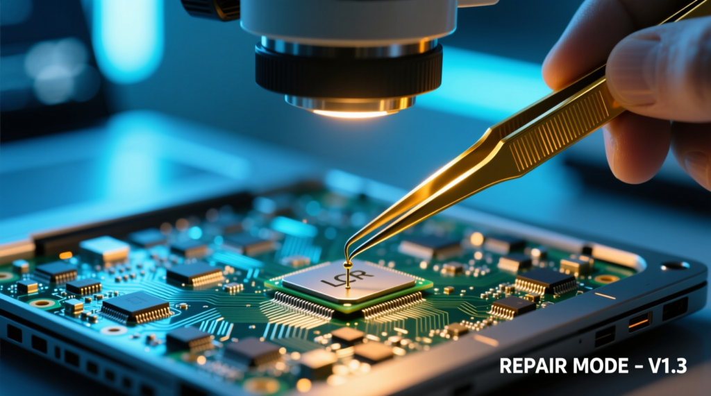
Put the board under the microscope first. Look for cracked packages, corrosion, solder bridges, burned pads, and missing components. Identify whether the capacitor is an MLCC or a polarized tantalum part. Tantalum capacitors are marked with a stripe or a “+” symbol.
Testing a tantalum capacitor with the wrong polarity can damage it, so know what you are touching before the tweezers close.
Safe Power-Down and Rail Discharge
Power off the laptop and disconnect every power source, including the battery and charger. Press the power button a few times to discharge residual rail voltage. Never probe a live rail.
Frequency and Voltage Selection Matrix
| Test Frequency | Best Used For |
|---|---|
| 100 Hz | Large electrolytic capacitors and high-capacitance MLCCs |
| 1 kHz | General-purpose ceramic and tantalum capacitors |
| 10 kHz | Low-value ceramic capacitors below 1 nF and high-frequency decoupling caps |
| Test Voltage | Best Used For |
|---|---|
| 0.3 V | In-circuit screening; avoids forward-biasing silicon junctions |
| 0.6 V | Out-of-circuit or high-impedance components where higher sensitivity helps |
In-Circuit Screening with the LCR-ST1
Set the FNIRSI LCR-ST1 to the frequency that matches the expected capacitor value and to 0.3 V for in-circuit work. Grip the capacitor across both pads with the gold-plated tweezer tips. Keep the tips clear of adjacent components, especially around dense CPU and GPU VRM regions.
Read the value, but treat it as equivalent network impedance. If the number looks off, it may be a parallel path, not a bad capacitor.
Definitive Out-of-Circuit Verification
When an in-circuit reading is suspect, lift one leg or remove the capacitor entirely. Use the hot-air rework station for safe removal. Once the part is isolated, measure it again and compare the value against the schematic or a known-good part. This is the only way to be certain.
Replacement and Trace Repair
Replace the capacitor with an equivalent capacitance, voltage rating, and dielectric type. Common dielectrics include X5R, X7R, C0G/NP0, and tantalum. For trace repair, use 40 AWG Micro-Thin Jumper Wire.
Check out TECH Collection Amazon Products
For soldering and rework:
- Soldering iron: 300–350 °C for leaded solder.
- Hot-air rework: 300–400 °C with airflow of 3–8 L/min, adjusted for the thermal mass of the package.
Field Verdict & Operational ROI
Diagnostic Speed and Misdiagnosis Reduction
The FNIRSI LCR-ST1 plus microscope workflow removes the guesswork. Selectable frequency and the 0.3 V in-circuit mode cut down on unnecessary component removal. You stop chasing phantom shorts and start replacing the actual failed part.
Total Cost-of-Ownership vs. Board Replacement
A focused diagnostic stack costs far less than a motherboard replacement. It also prevents the collateral damage that comes from stabbing around a dense board with oversized probes or blindly swapping capacitors.
Community-Validated Pitfalls Solved
- In-circuit false readings are handled with lift-one-leg verification.
- Test frequency confusion is resolved by matching 100 Hz, 1 kHz, or 10 kHz to the capacitor type.
- Probe tip durability is addressed by the gold-plated precision tips.
- The low-voltage necessity is met by the 0.3 V in-circuit mode.
- Tantalum versus MLCC identification is emphasized before testing.
- ESR misunderstanding is clarified: the FNIRSI LCR-ST1 measures L, C, and R, but it is not a dedicated ESR meter.
- The microscope requirement is treated as mandatory, not optional.
Conclusion
Community Reference & Authority Resources:
Testing SMD capacitors on a laptop motherboard does not require a lab full of bench gear. It requires the right tool for the package size, the right test conditions for the circuit, and the discipline to verify suspicious readings out-of-circuit.
The FNIRSI LCR-ST1 gives you the selectable frequency, the 0.3 V in-circuit-safe mode, and the precision tips to handle 0201 through 1206 packages. Paired with a microscope for visual inspection and a hot-air station for removal, it turns a frustrating guessing game into a repeatable diagnostic process. Stop replacing motherboards. Start isolating the actual failure.
🔍 Explore More: See all tech guides and tutorials for how to test SMD capacitors on laptop motherboard using FNIRSI LCR-ST1.
Check out TECH Collection Amazon Products