
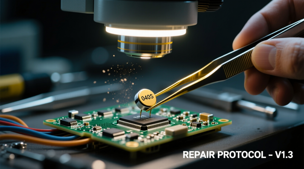






When it comes to step by step guide finding short circuit on motherboard using LCR tweezers and power supply, getting the right details matters. Recommended Products:
FNIRSI LCR-ST1 Smart LCR Tweezers
Siglent SPD3303X-E Programmable DC Power Supply
Andonstar AD246S-M HDMI Digital Microscope
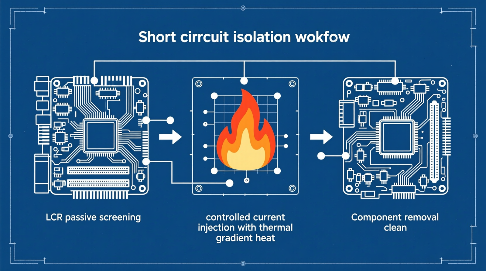
A dead motherboard with a rail-to-ground short is not a guessing game. It is a controlled hunt for an unintended low-resistance path that is stealing current before it can reach the CPU, RAM, or chipset. This guide shows you how to isolate that fault safely and repeatably using smart LCR tweezers, a current-limited bench power supply, and a high-clearance inspection microscope. You will learn how to read the board, screen individual SMDs, inject controlled current, and verify the repair without turning a simple short into a destroyed PCB.
The Technical Reality — What a Motherboard Short Actually Is and Why It Hides
The Failure Class: Low-Resistance Rail-to-Ground Conduction on Multi-Layer PCBs
A motherboard short is an unintended low-resistance path between a power rail (VCC, VIN, or a VRM phase) and ground. On a multi-layer PCB, that path can sit inside the board stack, under a metal shield, or inside a tiny SMD that looks perfectly normal.
The practical impact is immediate: the rail sees a resistance to ground of <1 Ω or near 0 Ω, so the power supply dumps current into the fault instead of the load. That triggers overcurrent protection, thermal runaway, or a board that shuts down before it even considers POST.
The Physical Root Causes That Create the Short
MLCC failures: Shorted multilayer ceramic chip capacitors in CPU/GPU VRM decoupling networks are the classic culprit. A single failed MLCC can pull an entire rail to ground.
Active-device failures: Failed MOSFETs, Schottky diodes, and synchronous buck regulators in power-delivery stages can create a direct rail-to-ground path.
Manufacturing or handling defects: Solder bridges, tin whiskers, and conductive flux residue under fine-pitch ICs and QFN packages create shorts that survive initial testing.
Board-level damage: Cracked or delaminated PCBs, or damaged internal via barrels, create rail-to-ground leakage that is invisible from the surface.
Environmental damage: Liquid ingress and corrosion around battery connectors, USB ports, and charging ICs leave conductive paths that grow worse over time.
Observable Symptoms That Point to a Rail-to-Ground Short
The main fuse, polyfuse, or current-limit circuit trips the instant power is applied. The board fails to POST, and you feel localized heat at the DC-in port or regulator area. Your bench power supply current limit saturates at a very low output voltage, often under a volt.
The Measurement Confounders That Make Shorts Hard to Isolate
In-circuit parallel paths produce false low-resistance readings. A shorted capacitor can make a healthy MOSFET look bad, and vice versa.
Standard multimeter probes lack the mechanical precision to reliably contact 0201/0402/0603 components. High test voltage on semiconductor junctions forward-biases adjacent components, giving you misleading LCR readings that send you chasing the wrong part.
The Core Gear Architecture — The Validated Diagnostic Stack
Smart LCR Tweezers: FNIRSI LCR-ST1
The FNIRSI LCR-ST1 is the screening tool. Its job is to measure the passive signature of individual SMDs without lifting every part.
| Feature | Specification |
|---|---|
| Display | 1.14-inch color display |
| Weight | 41 g |
| Test Frequencies | 100 Hz / 1 kHz / 10 kHz |
| Test Voltages | 0.3 V (in-circuit safe) / 0.6 V (standard) |
| Battery | 250 mAh lithium, USB-C charging |
| Tips | Gold-plated micro-tips for small SMD access |
| Measurement Modes | Resistance, capacitance, inductance, diode measurement |
The 0.3 V test voltage matters because it is low enough to avoid turning on adjacent silicon.
At 0.6 V, you risk forward-biasing diodes and MOSFET body diodes, which makes a healthy rail look shorted. The 100 Hz / 1 kHz / 10 kHz frequency set lets you match the test signal to the component: 100 Hz for large electrolytics, 1 kHz for general ceramics and resistors, and 10 kHz for small-value inductors and capacitors.
Current-Limited Bench DC Power Supply: Siglent SPD3303X-E
The Siglent SPD3303X-E is the localization tool. It injects a controlled current into the shorted rail so the fault zone reveals itself through heat.
| Feature | Specification |
|---|---|
| Channels | 3 (CH1/CH2 variable, CH3 fixed) |
| Output | CH1/CH2 0–32 V / 0–3 A |
| Total Power | 220 W |
| Resolution | 10 mV / 10 mA |
| Ripple | <350 µVrms |
| Modes | Constant-voltage/constant-current |
| Protection | Over-voltage, over-current, over-temperature |
| Operation | Series/parallel operation support |
The 10 mA current-resolution and precise constant-current mode are what separate a safe diagnostic injection from a trace-burning mistake.
The <350 µVrms ripple keeps noise from masking the tiny voltage gradients you need to measure across a shorted rail.
High-Clearance Inspection Microscope: Andonstar AD246S-M
The Andonstar AD246S-M is the visual confirmation tool. You cannot fix what you cannot see, and modern motherboards hide faults under shields and inside 0402 packages.
| Feature | Specification |
|---|---|
| Display | 7-inch LCD |
| Video | 2160P |
| Vertical Clearance | 30 cm high bracket |
| Output | Dual-screen HDMI (local + external) |
| Optics | Three interchangeable lenses |
| Lighting | LED ring illumination |
The 30 cm vertical clearance and 2160P output matter because they give you room to work. A soldering iron or hot-air nozzle needs space under the lens, and the dual-screen HDMI output lets a second technician or camera follow the action.
Trace Repair Consumable: 40 AWG Enamel-Coated Copper Jumper Wire
Conductor diameter: 0.079 mm. Application: Bridge severed traces after short removal. The 40 AWG / 0.079 mm diameter is thin enough to route under nearby components without adding mechanical stress or unwanted capacitance.
Freshness Upgrades That Matter for This Workflow
LCR tweezers: USB-C charging, firmware-upgradeable measurement algorithms, and a selectable 0.3 V low-voltage in-circuit mode to avoid turning on adjacent semiconductor junctions. Bench power supply: Low-ripple regulation, remote-sense terminals, and 10 mA current-resolution limiting for safe injection into low-impedance rails. Microscope: 2160P dual-HDMI output and 30 cm vertical clearance as baseline for hot-air rework and soldering-iron access under magnification.
The Technical Setup Blueprint — Step-by-Step Short-Circuit Localization
Pre-Flight Safety and ESD Protocol
Before you touch the board, lock down the environment. Use a current-limited supply. Never connect an unregulated source to a shorted rail. Wear an ESD wrist strap and work on an anti-static mat. Keep in-circuit test voltage ≤0.6 V to avoid damaging sensitive silicon. Ensure tweezers tips are clean, aligned, and free of oxidation or gap-related contact-resistance errors.
Phase 1 — Visual Inspection Under the Andonstar AD246S-M
Check out TECH Collection Amazon Products
Use 2160P magnification with 30 cm bracket clearance. Scan for burned components, solder bridges, corrosion, or discolored MLCCs. Remove metal shields, thermal pads, or obstructions that hide the fault zone. A surprising number of shorts are visible once you have the magnification and lighting to see them.
Phase 2 — Passive Component Screening with the FNIRSI LCR-ST1
Set the tweezers correctly before you probe: 0.3 V test voltage for in-circuit measurements. 100 Hz for large electrolytic capacitors. 1 kHz for general ceramic capacitors and resistors. 10 kHz for small-value inductors and capacitors.
Probe each SMD in the suspect rail. Compare readings to a known-good board or the datasheet. Flag abnormally low resistance, reversed or short diode readings, or capacitance far outside tolerance. Remember that a shorted capacitor can make a healthy MOSFET look shorted, so treat in-circuit readings as directional hints, not verdicts.
Phase 3 — Current Injection and Thermal Localization with the Siglent SPD3303X-E
Set the supply for controlled injection: Constant-current mode, initial limit 0.1–0.5 A. Output voltage 1–2 V, just enough to push current through the short. Connect the supply positive to the shorted rail and negative to ground. Gradually raise the current while monitoring the voltage. The fault will heat up.
Localize it with one of these methods: Thermal camera for fastest and safest detection. Isopropyl alcohol evaporation where the fastest-drying spot is the hottest. Voltage-drop probing to measure across sections of the rail and find where the voltage collapses.
Phase 4 — Verification and Repair
Remove the suspected component with hot-air rework at a controlled temperature. Retest the rail resistance with the LCR tweezers or a multimeter. If trace damage exists, bridge it with 40 AWG enamel-coated jumper wire. Re-test under current-limited power before applying full operating voltage. Do not rely on a single in-circuit measurement; lift one leg of suspect components for definitive testing.
Field Verdict & Operational ROI — Why This Stack Earns Its Place on the Bench
How the Stack Solves Real Forum Pain Points
This setup eliminates the erratic readings that plague cheap tweezers. The gold-plated micro-tips and true 0.3 V low-voltage in-circuit mode give reliable readings on 0201/0402/0603 parts. It overcomes false parallel-path readings by combining LCR screening with current-limited thermal localization. You stop guessing and start isolating.
The Cost of Getting the Diagnosis Wrong
Unregulated current injection burns PCB traces and delaminates pads. Misidentified shorts lead to unnecessary component replacement and secondary damage. Inadequate magnification causes missed solder bridges or corrosion under shields. The wrong tools do not just slow you down; they destroy the board you are trying to save.
The Technician’s Bottom Line
The FNIRSI LCR-ST1, Siglent SPD3303X-E, and Andonstar AD246S-M form a fault-isolation system that converts “where is the short?” into a repeatable, safe, and verifiable workflow. Investment in current-limited injection and precision in-circuit measurement pays for itself by preventing board destruction and reducing diagnostic time.
Community Reference & Authority Resources:
Conclusion
Finding a short on a motherboard is not about luck. It is a disciplined progression from visual inspection to passive screening to controlled current injection and final verification. The right tools make the difference between a five-minute capacitor replacement and a permanently damaged board. With the FNIRSI LCR-ST1 for precise component screening, the Siglent SPD3303X-E for safe current-limited localization, and the Andonstar AD246S-M for clear visual confirmation, you have a complete diagnostic system that turns a hidden rail-to-ground fault into a solved repair. Set up your bench, keep the current limited, and verify every reading before you commit the soldering iron.
🔍 Explore More: See all tech guides and tutorials for step by step guide finding short circuit on motherboard using LCR tweezers and power supply.
Check out TECH Collection Amazon Products