
Advanced laptop motherboard failures often present as “no power,” “no boot,” or intermittent operation, defying simple component replacement. 😩
Unlike desktop motherboards, laptop PCBs are highly integrated, multi-layered, and densely packed, making diagnosis and repair a specialized field known as component-level repair. 🔬
Effective troubleshooting requires a deep understanding of power delivery systems, component-level diagnostics, and the use of specialized tools, moving far beyond basic plug-and-play fixes. 🛠️
This article outlines the systematic approach to diagnosing and isolating complex laptop motherboard faults, transforming frustration into a successful repair. 🚀
As Louis Pasteur once said, “Chance favors only the prepared mind.” Preparation is everything when facing a complex fault. 🧠
I. Safety, Setup, and Initial Assessment 📌
Before touching any component, proper safety and setup are mandatory.
This work is meticulous and deals with sensitive electronics.
A. Essential Safety and Work Environment
Electrostatic Discharge (ESD) protection is non-negotiable. ⚡
Always wear an ESD wrist strap connected to a reliable ground point.
Work on an anti-static mat to protect the motherboard from sudden voltage spikes that can instantly destroy integrated circuits.
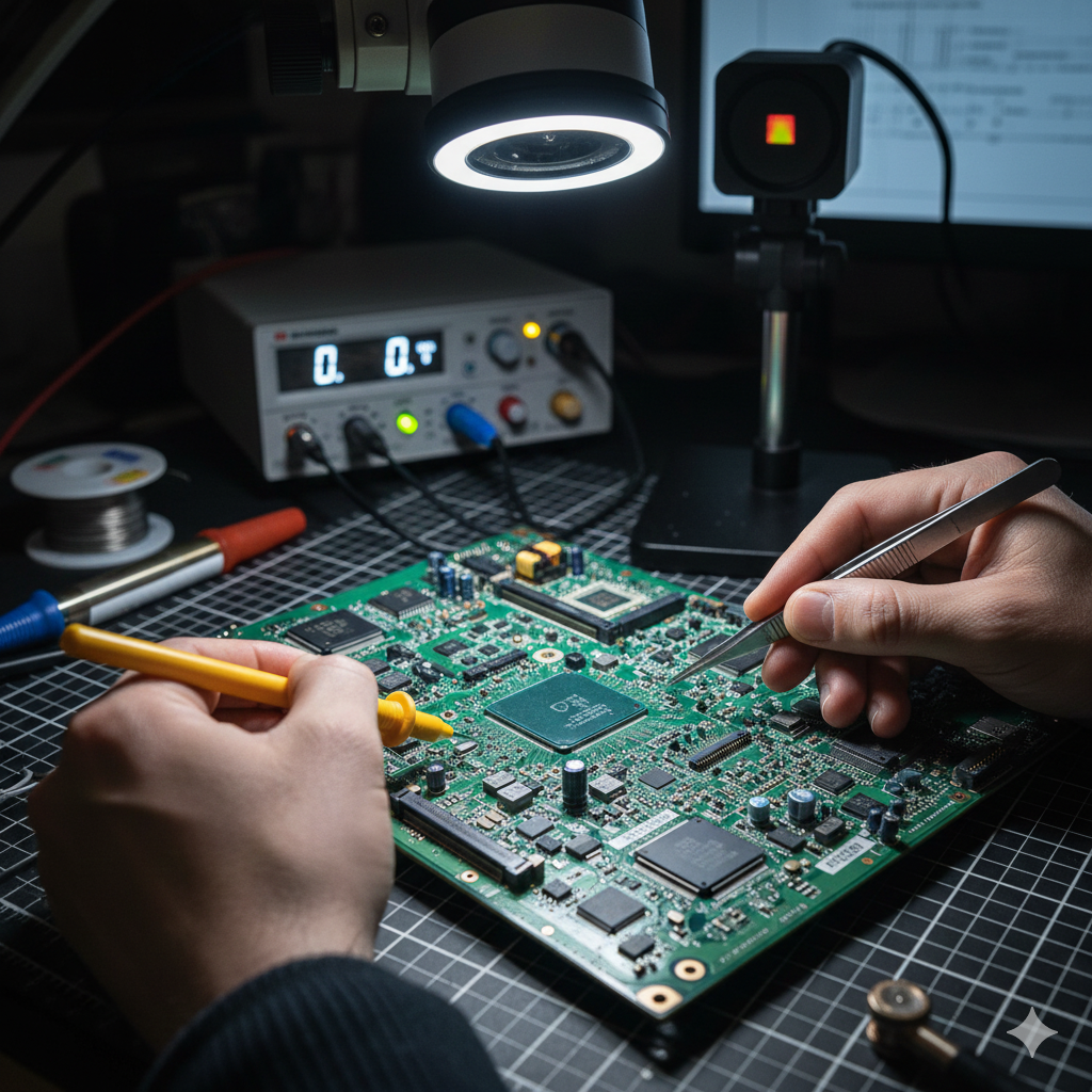
Good lighting and magnification (a stereo microscope is ideal) are crucial for inspecting and working on tiny components.
B. Initial Checks and Visual Inspection
Always start with the simplest checks.
1. External Power: Verify the power adapter is supplying the correct voltage (e.g., 19V, 20V) and current (Amps).
2. DC-in Jack: Check that the DC-in jack on the motherboard is not physically damaged or loose.
3. Visual Inspection: Look for obvious signs of failure: 🔍
Liquid damage (white or green residue, corrosion) is a primary cause of complex failures, bridging traces and causing shorts [1].
Burnt components (often MOSFETs or ICs) may leave a distinct smell or visible scorching.
Bulging or leaking capacitors indicate an issue in the power filtering system.
II. The Power-On Sequence: A Three-Stage Flow 💡
A laptop’s power-on sequence is a complex series of events, orchestrated by chips that generate and enable different voltage rails.
Failures often occur at specific stages, which can be identified through systematic voltage and signal measurements.
A. Stage 1: Always-On (S5 State)
These are the power rails that are active as soon as the power adapter is connected, even if the laptop is “off.” 🔋
The primary job of this stage is to create the essential low voltages that allow the system’s control chip to function.
- DC-In Circuit: The external voltage (e.g., V_IN) is first processed by the Charger IC (or BATT_FETS), which creates V_BATT (battery voltage) and the main system voltage (AC_DRV or Main Rail). This voltage is typically the same as the adapter voltage (19V).
- LDO Rails: The Charger IC or a dedicated PMIC creates the Always-On (LDO) rails, typically 3V and 5V. These are crucial because they power the Super I/O (SIO) chip and the BIOS chip.
- Key Checkpoint: Use the multimeter to confirm the presence of 3V/5V LDO on the SIO and the BIOS chip’s VCC pin. If these are missing, the issue lies in the Charger IC or the primary 3V/5V buck converter.
https://youtu.be/M-YlXkP_2S0
B. Stage 2: Standby Power (S4/S3 States)
This stage begins when the power button is pressed. 🟢
The Power Button signal travels to the SIO chip, which acts as the power gatekeeper.
- SIO Role: The SIO receives the button press and, if conditions are met (like a healthy Main Rail), it sends out enabling signals, such as SUS_PWR_EN (Suspend Power Enable).
- Standby Rails: These enable signals activate the secondary Power Management Integrated Circuits (PMICs), which generate the standby rails: VRAM (for system memory), VCC_GFX (GPU standby), and the main PCH/CPU standby rails.
- Key Checkpoint: Check if the Power Button Signal reaches the SIO (often a brief drop from 3.3V to 0V). If the signal is received but the standby rails don’t appear, the SIO or its programmed sequence may be faulty.
C. Stage 3: Main Power and POST (S0 State)
This is the final stage where all major components are powered and the system attempts to boot. 🚀
The PCH (Platform Controller Hub) takes over control from the SIO at this point.
- Main Power Rails: The PCH enables the high-current rails, notably VCORE (CPU core voltage), the most current-hungry rail on the board. Other rails like VPP and auxiliary chipset voltages are also activated.
- POST Sequence: The PCH initiates the Power-On Self-Test (POST), fetching instructions from the BIOS chip, which then hands control to the CPU. The SIO will send the PCH_PLT_RST (Platform Reset) signal.
- Key Checkpoint: If the laptop powers on (fans spin) but doesn’t show a display (No Boot), check for the presence of VCORE. If VCORE is present but the screen remains blank, the issue is likely BIOS/Firmware corruption or a PCH/CPU failure.
| Power State (ACPI) | Status / Description | Critical Rail Examples | Failure Symptom |
|---|---|---|---|
| S5 (G3) | Mechanical Off / Adapter Connected. SIO and BIOS are powered. | V_IN (19V), 3V/5V LDO | No LEDs, 0V on power button. |
| S4 / S3 | Sleep / Standby / Power Button Pressed. RAM and PCH standby rails activate. | VRAM, PCH Standby (1.05V), SUS_PWR_EN signal | Power button light flashes, no fan spin. |
| S0 | Full On / Operating. CPU receives full power, POST runs. | VCORE, VGFX (CPU/GPU Core), PCH_PLT_RST signal | Turns on but no display, frequent power cycling. |
III. Component-Level Fault Isolation 💥
When voltage measurements indicate a rail is missing or showing a low resistance to ground, a short circuit is the likely culprit.
The goal is to find the single component that is shorting the entire power line.
A. Short Circuit Detection and Resistance Measurement
The first step in isolating a short is to measure the resistance to ground. 📏
With the power off and the battery disconnected, set the multimeter to resistance (\Omega) mode.
Measure the resistance between the suspected power rail (often an inductor coil) and a known ground point on the board.
A very low resistance (near 0 \Omega) confirms a short to ground.
Typical components that short include ceramic capacitors (often damaged by mechanical stress or heat), MOSFETs, and sometimes the ICs themselves.
B. Thermal Imaging and Voltage Injection
This is the most effective and least destructive method for isolating a short. 🌡️
1. Voltage Injection Setup: Use a DC lab power supply to inject a low, current-limited voltage (e.g., 1V to 3V) into the shorted rail.
Crucially, the current must be limited (e.g., 1A to 5A) to prevent further damage.
The injected voltage must be equal to or less than the rail’s nominal voltage to avoid damaging other components connected to that line.
2. Thermal Identification: The faulty component acting as the short will heat up rapidly due to the high current flowing through it.
Use a thermal camera to visually identify the hot spot immediately [2].
In the absence of a thermal camera, the “IPA trick” (spraying Isopropyl Alcohol on the suspected area, the shorted component will cause the IPA to evaporate instantly) can be used as a low-cost alternative.
Warning: Never inject the full adapter voltage into a shorted low-voltage rail!
https://youtu.be/kU9uHkL5r7E
IV. Software Faults: BIOS and Firmware Corruption 💾
A “no boot” or “power cycling” issue without a clear hardware short can often be traced to a corrupted BIOS chip.
The BIOS (Basic Input/Output System) holds the initial instructions for the system boot process.
A. Diagnosis and Symptoms
A corrupted BIOS can manifest in several ways:
- The system powers on (fans spin) but fails to initiate the POST sequence (no display).
- The laptop exhibits a power-cycle loop, turning on and off rapidly.
- Certain voltage rails (like VCORE) may briefly appear and then disappear.
B. Repair: Using an SPI Programmer
Repairing a corrupted BIOS requires a specialized tool called an SPI (Serial Peripheral Interface) programmer.
1. Locating the Chip: The BIOS chip is usually an 8-pin or 16-pin SPI flash chip found near the SIO or PCH.
2. Reading/Writing: The programmer is connected to the chip using a clip or by soldering fine wires. The technician must first read the existing corrupt data (for backup) and then erase the chip.
3. Flashing the Firmware: A clean, verified BIOS file (often downloaded from the manufacturer, stripped of the update header, and sometimes requiring a “Clean ME Region” correction) is then written (flashed) onto the chip.
This procedure is a key skill in non-hardware motherboard repair.
As Dwight D. Eisenhower once stated, “Planning is everything; the plan is nothing.” Having a systematic diagnostic plan is far more important than any single tool.
V. The Ultimate Challenge: PCH and CPU Failure 🌋
The Platform Controller Hub (PCH) or the CPU itself (often integrated into a single BGA package) can fail due to overheating, power surges, or manufacturing defects.
These are the most advanced repairs.
A. Diagnosis of Chipset Failure
When a PCH fails, the system may pass the initial power-on checks (LDO rails are present) but fail to progress, showing a No Boot symptom even after a successful BIOS reflash.
A common sign of a PCH failure is its inability to correctly manage the reset signals or if it shows a dead short on its own internal power rails.
CPU failure is rare but catastrophic, typically causing an immediate short on the VCORE rail or halting the POST sequence entirely.
B. BGA Rework and Replacement
Replacing a PCH or CPU requires BGA (Ball Grid Array) rework equipment. 🏗️
- BGA Rework Station: This specialized machine uses highly precise top and bottom heating elements to melt the thousands of tiny solder balls beneath the chip without damaging the surrounding components or the motherboard itself.
- Reballing: After the old chip is removed, the contact pads must be cleaned, and the new chip must be “reballed”—a process of attaching new, perfectly spherical solder balls to its underside using a stencil.
This is a highly advanced and specialized procedure that requires significant training and is considered the pinnacle of component-level laptop repair [3].
https://youtu.be/P1r_E-sX8M8
VI. Essential Tools and Methodology 🧰
To summarize, success in advanced troubleshooting depends on having the right tools and a meticulous methodology.
- Digital Multimeter: For measuring voltage and resistance to ground (the most fundamental tool).
- DC Lab Power Supply: Essential for safe voltage injection during short circuit isolation.
- Thermal Camera: The fastest, most effective tool for pinpointing a shorted component.
- Stereo Microscope: Necessary for detailed visual inspection and micro-soldering.
- SPI Programmer: For diagnosing and repairing BIOS/firmware corruption.
- Schematics/Boardview Software: These provide circuit diagrams and component locations, which are absolutely critical for tracing power rails and finding nominal voltages. Never attempt advanced repair without a schematic!
VII. External References and Further Learning 📚
For more detailed information and advanced troubleshooting:
Lapserve: Top 5 Reasons for your Laptop Motherboard Malfunctions
Tom’s Guide: Laptop Motherboard Diagnosis/Repair (No Power)
iFixit: How to Use a Multimeter for Basic Electronics Testing
All About Circuits: Understanding Voltage Regulators (PMICs)
PCBWay: How to Read a PCB Schematic
Conclusion 🎉
Advanced laptop motherboard troubleshooting is a meticulous process that moves from macro-level visual inspection to micro-level voltage and resistance measurements. 🤓
By systematically checking the power-on sequence and isolating short circuits using thermal methods, technicians can perform component-level repairs, saving the motherboard from costly replacement.
Mastery of this skill is what separates the technician from the true repair specialist. 💪
Embrace the complexity, trust your meter, and keep learning!
The most rewarding fixes are often those that require the most patience and precision.