
An open circuit on a motherboard, often caused by a broken or damaged PCB trace, can seem like a death sentence for your hardware.
However, with the right tools and a steady hand, this is one of the most satisfying and creative fixes you can perform in electronics repair.
This guide will walk you through the professional and unconventional methods for diagnosing and repairing a broken trace, turning a seemingly junk board into a fully functional component.
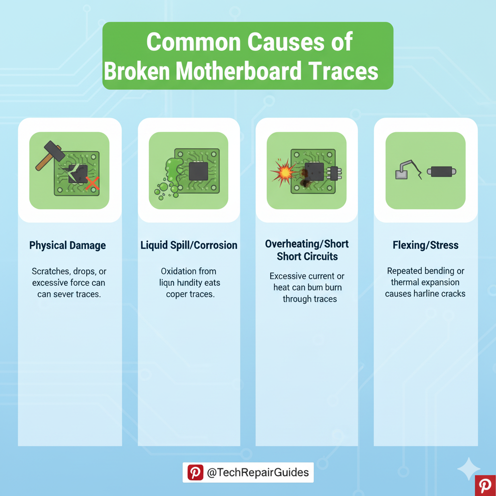
Understanding the Enemy: What is a Broken PCB Trace?
A Printed Circuit Board (PCB) trace is a thin strip of copper that acts as a wire, conducting electricity between components.
When this trace is physically damaged—scratched, burnt, or corroded—it creates a gap, resulting in an open circuit where current cannot flow.
The repair process is essentially bridging that gap with a new, reliable conductor.
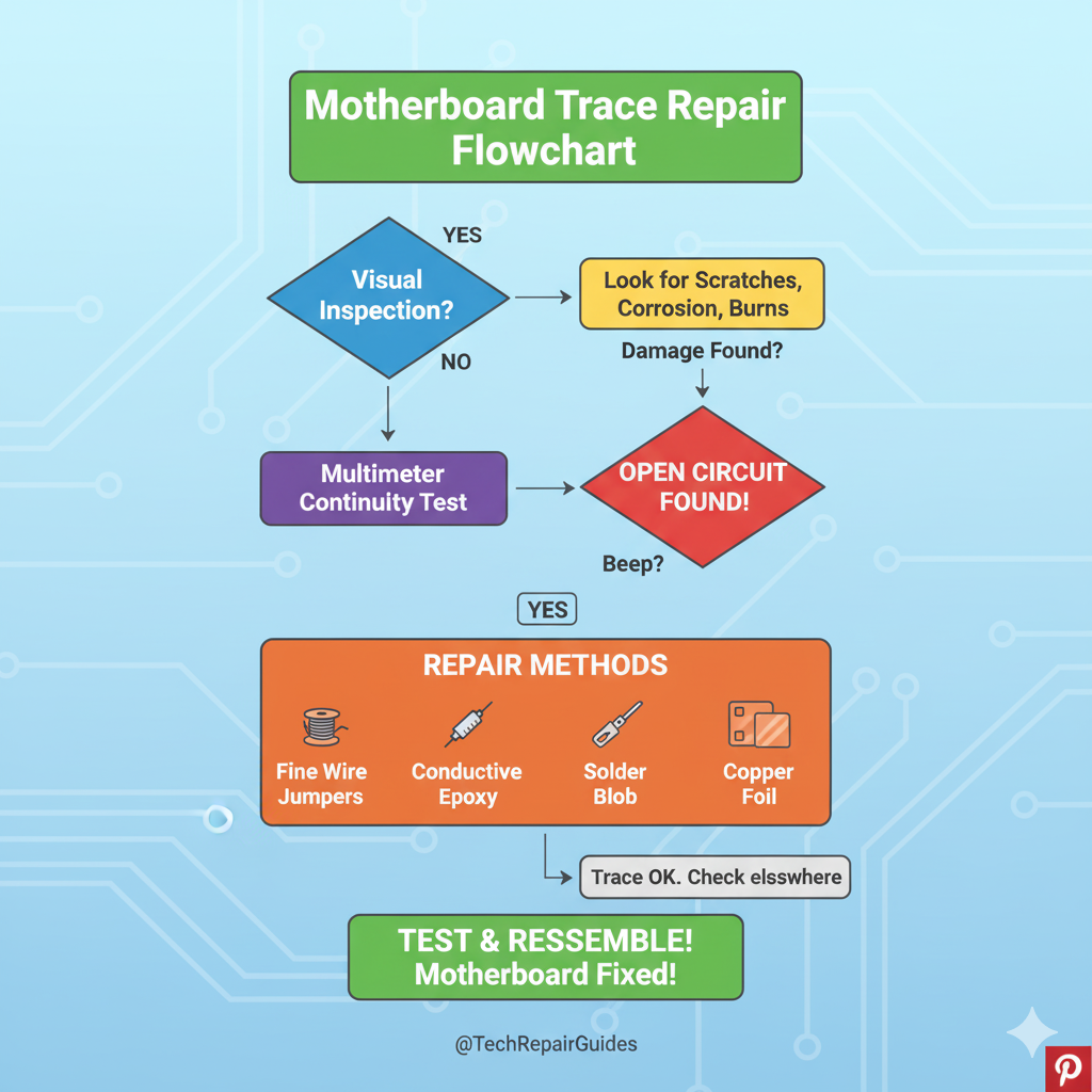
Phase 1: Diagnosis and Preparation
Before you can fix the trace, you must first find it and prepare the area for repair.
Step 1: Visual Inspection and Magnification
The first step is a thorough visual inspection, ideally under a microscope or a high-magnification loupe.
Look for thin, hairline scratches, burn marks, or corrosion that breaks the continuity of the copper line.
A common cause is accidental damage during component removal or a short circuit that vaporized a section of the trace.
Step 2: Continuity Testing with a Multimeter
Use a multimeter set to continuity mode to confirm the break.
Place the probes on either side of the suspected break.
A healthy trace will beep, indicating continuity (a closed circuit).
A broken trace will remain silent, confirming the open circuit.
Step 3: Exposing the Copper
The copper trace is protected by a layer of green (or other color) solder mask.
You must carefully and gently scrape away the solder mask on both sides of the break to expose a clean, bright section of copper.
This exposed copper will serve as the anchor point for your repair material.
Use a fiberglass pen, a sharp hobby knife, or a fine-grit abrasive tool for this delicate task.
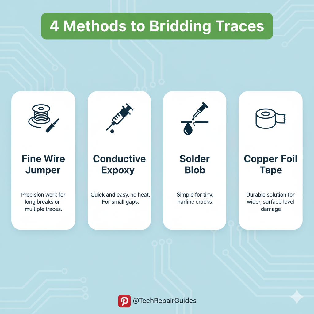
Phase 2: Creative Repair Techniques (The Fix)
There are several creative ways to bridge the open circuit, depending on the trace width, location, and your available tools.
Method 1: The Wire Bridge (The Professional Standard)
This is the most common and reliable method, especially for power and ground traces.
Use a piece of fine, insulated magnet wire (also known as enamel wire) that is thin enough for the job but robust enough to carry the required current.
Steps for Wire Bridging:
- Tin the exposed copper pads on both sides of the break with a small amount of solder.
- Strip the enamel from the ends of your magnet wire and tin the ends.
- Carefully solder one end of the wire to the exposed copper on one side of the break.
- Route the wire neatly over the damaged area and solder the other end to the exposed copper on the opposite side.
- Trim any excess wire.
Method 2: Conductive Silver Epoxy (The Quick Fix)
For very fine signal traces where soldering is too risky, or for a quick, low-stress repair, conductive silver epoxy or conductive pen can be used.
This material contains silver particles that conduct electricity once cured.
Steps for Epoxy Repair:
- Ensure the exposed copper is clean and free of flux residue.
- Carefully apply a small amount of the conductive material to bridge the gap, ensuring it overlaps the healthy trace on both sides.
- Allow the material to cure completely according to the manufacturer’s instructions (often 24 hours or with heat).
Method 3: Copper Foil Tape (The Wide Trace Solution)
For wide traces, such as those in power planes or ground planes, copper foil tape with conductive adhesive can be a fast and effective solution.
Simply cut a piece of the tape to size, ensuring it covers the break and adheres firmly to the exposed copper on both sides.
Phase 3: Post-Repair and Protection
Once the circuit is closed, the repair must be tested and protected.
Step 1: Final Continuity Test
Re-test the repaired trace with your multimeter to confirm continuity.
You should now hear the beep, indicating a successful repair.
Step 2: Applying Solder Mask (The Professional Finish)
To protect the exposed copper and the repair from corrosion, short circuits, and physical damage, you must apply a new layer of solder mask.
UV-curable solder mask is the standard choice.
Apply a thin layer over the repair and cure it using a UV light source.
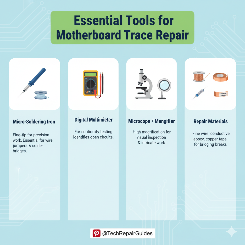
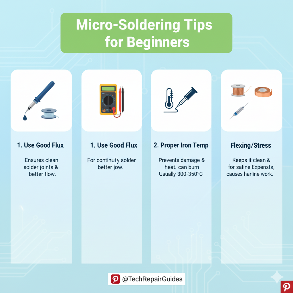
Essential Tools for Motherboard Trace Repair
To perform these intricate repairs, you will need specialized equipment:
- Microscope or Magnification Lamp: Essential for seeing the fine traces.
- Fine-Tip Soldering Iron: A temperature-controlled iron with a very fine tip (e.g., a J-tip or chisel tip).
- Fine Magnet Wire: 30-40 AWG is ideal for most traces.
- UV-Curable Solder Mask: For protecting the final repair.
- Fiberglass Pen or Hobby Knife: For carefully scraping away the original solder mask.
- Multimeter: For diagnosing the open circuit and testing the final repair.
Video Resources: See the Repair in Action
To truly master this skill, watching the process is invaluable.
We have curated two long-form YouTube videos that demonstrate these techniques in detail.
Conclusion: The Satisfaction of the Fix
Repairing a broken PCB trace is a high-level skill that requires patience and precision.
By following these steps and practicing the creative techniques of wire bridging and conductive material application, you can confidently save valuable hardware and gain immense satisfaction from the fix.
References
[1] The Ultimate Guide to PCB Trace Repair: Step by Step for Engineers
[2] How to Fix Burnt Traces on a PC Motherboard
[3] How To Repair Broken PCB TRACE – Learn 4 Different Methods