

Surface Mount Devices (SMDs) are the unsung heroes of modern electronics. 💡
They enable the compact, powerful gadgets we use every day, from smartphones to smart home devices. 📱
However, their minuscule size, while advantageous for manufacturing, presents a significant challenge when it comes to troubleshooting and repair. 🔬
Diagnosing a faulty SMD component on a densely packed Printed Circuit Board (PCB) requires precision, patience, and the right tools. 🛠️
Among these tools, the Digital Multimeter (DMM) stands out as an indispensable companion for any electronics enthusiast or professional. 🤓
While often associated with larger, through-hole components, a DMM, when used correctly, can be incredibly effective for pinpointing issues in the tiny world of SMDs. 📌
This comprehensive guide will equip you with the knowledge to accurately test common SMD components directly on a PCB using a standard DMM. ✅
We’ll delve into the essential multimeter settings, component-specific testing techniques, and crucial best practices for in-circuit measurements. 📚
By the end of this article, you’ll have a solid understanding of how to approach SMD diagnostics with confidence and precision. 💪
I. The Importance of Precision in SMD Testing 🎯
Before diving into the specifics, it’s crucial to appreciate the unique challenges presented by SMD components. 🤔
Their small footprints mean that probe placement must be incredibly accurate to avoid shorting adjacent pads or components. 🤏
Using standard multimeter probes can be cumbersome and risky. ⚠️
For this reason, investing in fine-tipped probes or specialized tweezers-style probes is highly recommended. 📌
These specialized probes offer better control and contact, significantly reducing the chances of error and potential damage to the PCB. 👍
Precision is not just about physical contact; it’s also about understanding the electrical environment. ⚡
In-circuit testing, while convenient, comes with inherent limitations due to parallel components that can influence your readings. 🔄
We’ll explore how to mitigate these factors to get the most accurate diagnostic information possible. 💡
II. Essential Multimeter Settings for SMD Testing ⚙️
Your DMM is a versatile tool, but knowing which mode to use for each component type is paramount. 🛠️
Here’s a breakdown of the essential modes and what to expect when testing various SMD components. 👇
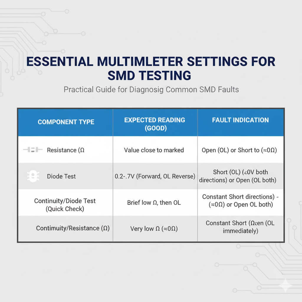
| Component Type | DMM Mode | Expected Reading (Good Component) | Common Fault Indication |
|---|---|---|---|
| Resistor | Resistance (Ω) | Value close to marked resistance (within tolerance) | Open circuit (OL) or Short circuit (near 0 Ω) |
| Diode | Diode Test | Forward Voltage Drop (typically 0.2V to 0.7V) in one direction; Open Line (OL) in reverse | Short circuit (near 0V in both directions) or Open circuit (OL in both directions) |
| Capacitor | Continuity/Diode Test (Quick Check) | Brief continuity/low resistance, then quickly climbs to OL as the capacitor charges | Constant short circuit (near 0 Ω) or Open circuit (OL immediately) |
| Inductor | Continuity/Resistance (Ω) | Very low resistance (near 0 Ω) | Open circuit (OL) |
III. Component-Specific Testing Techniques 🧪
A. Resistors: The Foundation of Resistance 🎛️
Testing an SMD resistor is generally one of the more straightforward tasks. 📏
Set your DMM to the appropriate resistance range (e.g., 200Ω, 2kΩ, 20kΩ, etc.). 🔄
Carefully place the probes across the two ends of the resistor. 🤏
You should obtain a reading close to the marked resistance value. 💡
There are two key considerations when testing resistors. 👇
In-Circuit Measurement Accuracy 🚧
Measuring a resistor while it is still on the board can be inaccurate due to parallel components that might be connected across it. 🤯
The DMM will measure the total equivalent resistance of the parallel network, which will always be equal to or lower than the actual resistance of the resistor you are trying to test. ⬇️
For a precise measurement, especially if the value seems off, the component should ideally be desoldered from the circuit. 🛠️
This isolates the resistor, ensuring that your measurement reflects only its intrinsic resistance. ✅
For more insights on testing SMD resistors, you can check out discussions on platforms like Reddit’s AskElectronics community. 🔗
Understanding Tolerance 📊
All resistors have a specified tolerance, which indicates how much their actual resistance can deviate from their marked value. 🏷️
Common tolerances are 1%, 5%, or even 10%. 📈
Always account for this tolerance when interpreting your DMM reading. 🧐
For example, a 100Ω resistor with a 5% tolerance could legitimately read anywhere between 95Ω and 105Ω. ⚖️
If your reading falls outside this range, it’s a strong indicator of a faulty component. 🚩
B. Diodes and Transistors: Semiconductor Gatekeepers 🚦
The Diode Test mode on your DMM is invaluable for testing semiconductor devices like diodes and transistors. 💡
This mode applies a small, known voltage across the component and measures the resulting voltage drop. ⚡
Diodes ➡️⬅️
A good diode acts like a one-way valve for current. 🚧
When you place the red (positive) probe on the anode and the black (negative) probe on the cathode, the DMM should show a forward voltage drop, typically between 0.2V (for Schottky diodes) and 0.7V (for silicon diodes). ⚡
This indicates that current is flowing in the forward direction. ✅
Now, reverse the probes (red on cathode, black on anode). 🔄
A healthy diode should show an “Open Line” (OL) reading, indicating very high resistance and no current flow in the reverse direction. 🚫
If you get a near 0V reading in both directions, the diode is likely shorted. 💥
If you get an OL reading in both directions, the diode is open. ❌
Transistors (BJT/MOSFET) ⚡
Bipolar Junction Transistors (BJTs) can be thought of as two back-to-back diodes. ↔️
You can use the Diode Test mode to test the junctions between the Base-Emitter and Base-Collector. 🤓
For NPN transistors, place the red probe on the base and the black probe on the emitter, then the collector. 📌
You should see a forward voltage drop of approximately 0.6V for each junction. 💡
Reverse the probes, and you should see OL. 🔄
PNP transistors are tested similarly, but with the black probe on the base and the red probe on the emitter/collector. 💡
MOSFETs (Metal-Oxide-Semiconductor Field-Effect Transistors) are more complex to test with a basic DMM. 🧐
While you can use the Diode Test mode to check the body diode (between the drain and source), a full functional test often requires more specialized equipment or dynamic testing in-circuit. 📈
However, a DMM can still help identify blatant shorts or opens between the gate, drain, and source terminals. 🛠️
For more detailed information on testing PCB components, including transistors, with a multimeter, Viasion provides an excellent guide: How to Check PCB Components With Multimeter. 🔗
https://youtu.be/yS9_0qQzJb8
C. Capacitors: Storing and Releasing Charge 🔋
Testing SMD capacitors, especially the tiny ceramic ones, can be challenging with a basic DMM, as many DMMs lack a dedicated capacitance measurement mode. 😥
However, you can still perform a useful quick check. ⏱️
Quick Continuity Check (for shorts) ⚡
Set your DMM to continuity mode or a low resistance range. 🔄
When you place the probes across a good capacitor, especially one with a decent capacitance value, you should briefly see a low resistance reading. ⬇️
This indicates that the capacitor is charging from the DMM’s internal battery. 🔋
As it charges, the resistance reading should quickly increase and then revert to an “Open Circuit” (OL) or very high resistance. 📈
This charging and discharging behavior is characteristic of a healthy capacitor. ✅
If you observe a constant low-resistance reading (near 0Ω) after the initial brief dip, it’s a strong indicator that the capacitor is short-circuited. 💥
This is a common failure mode for ceramic capacitors and can cause significant problems in a circuit. 🚨
A permanently shorted capacitor will allow current to flow unimpeded, potentially disrupting power rails or other sensitive components. ⚡
If your DMM has a dedicated capacitance mode, it’s generally best to remove the capacitor from the circuit for an accurate measurement. 📏
In-circuit capacitance measurements are highly susceptible to interference from parallel components. 🚧
For a visual demonstration on testing SMD capacitors for shorts, check out this YouTube Short: SMD Capacitor Test With Digital Multimeter | Spot Shorted… 🔗
D. Inductors: Resisting Change 🌀
SMD inductors, often found in power supplies and filtering circuits, are relatively simple to test. 💡
An ideal inductor has very low DC resistance, essentially acting as a short circuit to direct current. ⚡
Set your DMM to the lowest resistance range (e.g., 200Ω or continuity mode). 🔄
Place the probes across the inductor’s terminals. 🤏
A healthy inductor should show a very low resistance reading, typically close to 0Ω. ✅
If your DMM shows an “Open Line” (OL) reading, it indicates that the inductor’s winding is broken, and the component is faulty. ❌
An open inductor will block current flow, disrupting the circuit’s intended operation. 🚫
https://youtu.be/M-sJj7O2eBw
IV. Best Practices for In-Circuit Testing 🧐
While removing components provides the most accurate readings, it’s not always practical or desirable. 😥
When performing in-circuit testing, adhering to certain best practices can significantly improve the reliability of your diagnostics. 👇
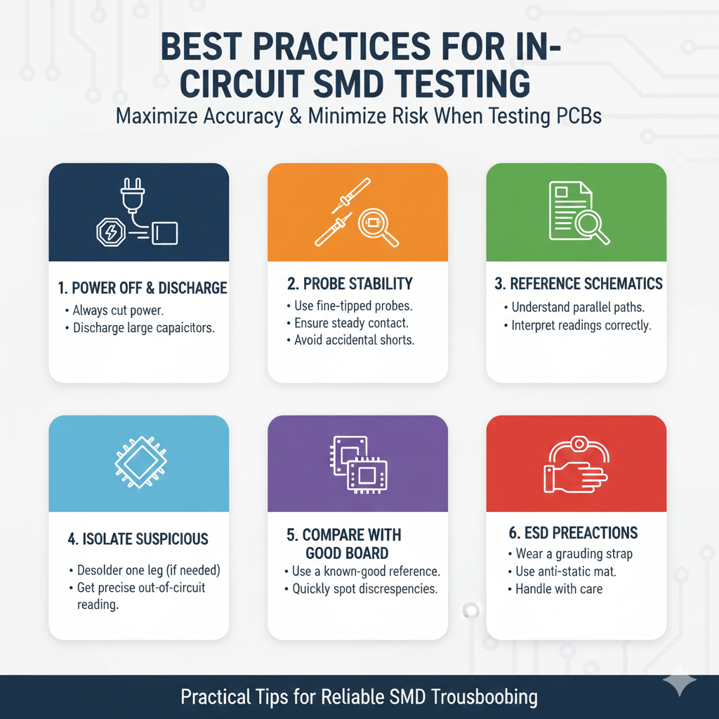
- Power Off and Discharge: Always, always, always ensure the circuit is completely powered off before commencing any testing. 🚫🔌 Furthermore, allow sufficient time for any large capacitors to discharge. Failure to do so can damage your DMM, the PCB, or even cause injury. ⚡
- Probe Stability and Contact: Due to the tiny size of SMDs, maintaining stable and consistent probe contact is critical. A shaky hand can lead to intermittent or erratic readings, making diagnosis impossible. Consider using specialized probe tips, test clips, or even a magnifying lamp to ensure good contact. Poor contact is a common source of false positives during troubleshooting. 🔍
- Reference Schematics: When in-circuit measurements provide ambiguous results, consult the circuit schematic if available. This will help you identify parallel paths that may be influencing your readings. Understanding the circuit’s layout is key to interpreting your DMM results accurately. 🗺️
- Isolate Suspicious Components: If a component consistently gives an unexpected reading even after considering parallel paths, it might be necessary to desolder one leg of the component. This effectively isolates it from the rest of the circuit, allowing for a precise out-of-circuit measurement. ✂️
- Compare with Known Good Boards: If you have access to a known good, identical PCB, use it as a reference. Comparing DMM readings between the faulty board and the good board can quickly highlight discrepancies and pinpoint faulty components. 🔄
V. Advanced Considerations and Limitations 💡
While a DMM is a powerful tool, it has its limitations, especially with complex SMD components and high-frequency circuits. 🤯
For example, some components like oscillators, microcontrollers, or complex ICs cannot be fully tested with a DMM alone. ⚙️
These often require specialized equipment like oscilloscopes, logic analyzers, or dedicated IC testers for proper diagnostics. 📈
Additionally, DMMs are primarily designed for DC measurements or low-frequency AC signals. 🌊
In high-frequency circuits, the parasitic capacitance and inductance of probes and the circuit itself can significantly distort readings. ⚡
Understanding these limitations is just as important as knowing the DMM’s capabilities. 🤓
Always choose the right tool for the job. 🛠️
VI. Prevention is Better Than Cure 🛡️
While troubleshooting is a vital skill, preventing component failures in the first place is always preferable. ✅
Many SMD component failures stem from improper soldering techniques, excessive heat, or electrostatic discharge (ESD). 💥
Using proper ESD precautions, such as grounding straps and anti-static mats, is crucial when handling PCBs. ⚡
Ensuring correct soldering temperatures and minimal dwell times can prevent heat damage to sensitive SMDs. 🔥
Regular maintenance and proper storage of electronic components can also extend their lifespan. 📅
Remember, a well-built and carefully handled circuit is less likely to require extensive troubleshooting. 🛠️
For more details on preventing issues and maintaining good soldering practices, consider resources like this guide from Fluke on how to use a multimeter effectively for diagnostics. 🔗
Conclusion: Mastering SMD Diagnostics 🎓
Mastering the art of testing SMD components with a multimeter is an invaluable skill for anyone involved in electronics repair or development. 🛠️
By understanding the correct DMM settings, applying component-specific testing techniques, and adhering to best practices for in-circuit measurements, you can significantly streamline your diagnostic process. 📈
Remember that precision, patience, and a systematic approach are your best allies in the tiny world of surface-mount devices. 🔬
While a DMM is incredibly powerful, always be aware of its limitations and know when to reach for more specialized equipment. 💡
With practice, you’ll gain the confidence to quickly and accurately diagnose SMD component failures, bringing those complex PCBs back to life. 🎉
Happy troubleshooting! 🥳