
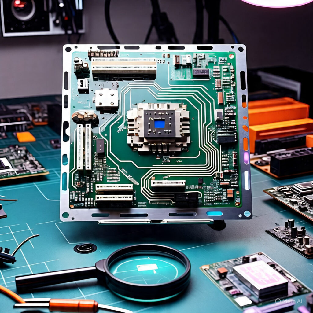
Circuit boards, also known as printed circuit boards (PCBs), serve as the backbone of most electronic devices,
providing a structured platform for connecting various components.
Their importance cannot be overstated, as they facilitate the flow of electrical signals that enable functionalities in everything from simple household appliances to sophisticated computers.
Understanding circuit boards is essential for anyone interested in electronics,
as they are responsible for establishing the paths through which signals travel from inputs to outputs.
A typical circuit board consists of multiple layers that house conductive pathways,
typically made of copper, which connect electronic components such as resistors, capacitors, and microchips.
The configuration of these components and the design of the PCB are crucial,
as they significantly influence the overall performance of the electronic device.
Effective circuit design ensures optimal signal integrity and helps mitigate issues such as interference,
which can lead to malfunctioning devices.
At the heart of any electronic device is the signal flow, which begins at an input point where data is received.
This signal, whether in analog or digital form,
travels through the circuit board, undergoing various transformations and processes determined by the components it encounters.
Understanding this journey from input to output is fundamental for troubleshooting and designing effective electronic systems.
As we delve deeper into the complexities of circuit boards,
it is vital to familiarize ourselves with key terminology and concepts, including voltage, current, and impedance.
Such knowledge will provide the foundational understanding necessary to navigate the intricacies of signal flow and component interactions effectively.
Upcoming sections of this guide will break down these concepts, making it easier to comprehend the critical role that circuit boards play in modern electronics.
Understanding Signal Flow
Signal flow refers to the path that an electrical signal takes as it travels through a circuit board,
starting from the input and eventually reaching the output.
Understanding this process is crucial for anyone working with electronic systems,
as it encompasses various stages of signal processing that collectively influence the performance and operation of the overall circuit.
The journey of the signal can be divided into three main stages: input, processing, and output.
The first stage, input, involves the generation of a signal from an external source, which can be a sensor,
a switch, or any device that produces an electrical signal.
This initial stage is critical because any noise or distortion introduced at this point can affect the entire signal journey.
High-quality connections and components are essential to maintain signal integrity and prevent degradation as the signal moves to the next phase.
The processing stage represents the core of signal flow, where the input signal undergoes various transformations.
These transformations can include amplification, filtering, and modulation, depending on the specific application of the circuit board.
Each of these processes is designed to enhance the desired characteristics of the signal while minimizing unwanted interference.
Careful design and consideration during this stage are paramount,
as they directly impact the clarity and accuracy of the output signal.
Finally, the output stage is where the processed signal is delivered to its destination,
whether it be another circuit, a display, or an actuator.
The nature of this stage can vary widely depending on the intended use of the signal,
but it is essential that the integrity is preserved throughout the flow of the 💒signal.
Whether transmitting data or controlling devices, the meticulous journey from input through processing to output illustrates that signal flow is vital for effective circuit operation,
highlighting the importance of each stage in maintaining optimal performance.
Videos will be added as random thoughts 💭 💭
Input Stage
The input stage of a circuit board serves as the critical entry point for external signals, initiating the process of signal processing and management.
During this stage, various types of signals, such as analog, digital, or mixed signals, are introduced into the circuit.
This portion of the circuit is pivotal because it sets the tone for how the signals will be handled throughout the rest of the system.
Ensuring a clean and stable input is essential, as any interference or distortion can have downstream effects that compromise the overall performance and reliability of the circuit.
To minimize potential issues, designers must consider the physical layout and components used in the input stage.
Factors such as signal integrity, impedance matching, and noise reduction become especially important.
For instance, the use of shielded cables can help reduce electromagnetic interference,
while proper grounding techniques can further bolster the circuit’s ability to maintain a clean input.
Additionally, it’s vital to account for the characteristics of the signals being introduced into the circuit.
Analog signals may require careful filtering to eliminate unwanted frequencies,
while digital signals need to be conditioned to mitigate any corruption caused by transition times and signal levels.
Another important aspect of the input stage is the role of components like operational amplifiers and comparators,
which can enhance signal quality by amplifying weak signals or converting them to digital form.
Understanding the specific requirements of the circuit board at this stage can prevent issues like signal degradation, which could lead to erratic performance.
By implementing comprehensive design practices at the input stage, engineers can establish a robust foundation for the subsequent processing stages of the circuit,
ultimately leading to more efficient and accurate signal handling.
This initial step is crucial in navigating the complex paths of circuit boards effectively.
Signal Processing Stages
Once a signal is input into a circuit board, it undergoes several critical processing stages,😘
each designed to refine and prepare the signal for its intended application.
Understanding these stages is essential for anyone involved in circuit design, troubleshooting, or maintenance.
The main processing stages typically include amplification, filtering, modulation, and signal conversion.
The first significant stage is amplification, where weak signals are boosted to useful levels.
This process is crucial as insufficient amplification can lead to signal degradation.
Common problems at this stage include distortion, which can arise from over-amplification,
or noise introduction due to poor circuit design or component selection.
Monitoring signal levels and employing high-quality components can help mitigate these issues.
Following amplification, the signal moves to the filtering stage,
where unwanted frequencies are removed.
Filters are designed to allow specific frequency ranges to pass while rejecting others.🤳
Incorrectly set filter parameters or component failures can result in the loss of critical signal information or the passage of undesired noise,
complicating subsequent processing stages.
Identifying the right filter characteristics is vital for achieving optimal signal clarity.
The modulation stage converts the signal into a suitable format for transmission or processing.
This could involve altering its characteristics,
such as amplitude or frequency, to facilitate effective communication over various media.
Problems during modulation can lead to miscommunication or loss of data integrity.
It is essential to ensure that modulation techniques align with the intended application to preserve signal fidelity.
Lastly, signal conversion involves transforming analog signals into digital forms or vice versa.
Accurate signal conversion is essential for interfacing different components or systems.
Common pitfalls in this stage include quantization noise and sampling errors that can distort the final output.
Regular calibrations and the use of high-resolution components can significantly enhance the reliability of signal processing.
In conclusion, by being alert to the common issues that can arise at each of these processing stages,
engineers and technicians can troubleshoot effectively,
ensuring robust performance of complex circuit boards throughout their operational life.
Output Stage
The output stage of a circuit board plays a crucial role in transmitting the processed signal to the next destination,
💝whether it be another circuit, a speaker, or a display.
This stage is integral to ensuring that the final output is not only accurate but also of high quality.
At this point, the signal that has been conditioned, amplified, or filtered is prepared for delivery.
Various components work together to achieve this goal,
including output
-
transistors,
-
operational amplifiers,
-
and interfacing circuits.
One of the key aspects of the output stage is impedance matching.
This process is vital as it ensures that the output of the circuit board can effectively 👇drive the load it encounters without excessive signal loss or distortion.
Impedance mismatches can lead to reflections of the signal, which can degrade the quality of the output.
Therefore, achieving proper impedance alignment is critical for maintaining the integrity of the signal as it exits the board.
Additionally, the architecture of the output stage needs to be designed to handle potential issues such as voltage drops and signal attenuation.
Engineers must ensure that any output circuitry is capable of providing the necessary power levels to drive connected devices without compromising performance.
The characteristics of the output stage must also be aligned with the specifications of the load,
which might include varying requirements based on the device’s nature,
such as resistive, capacitive, or inductive loads.
Lastly, monitoring the feedback from the output stage to adjust parameters dynamically can enhance performance further.
This feedback loop allows for real-time corrections,
helping to preserve the quality of the signal.
Overall, the careful design and execution of the output stage are paramount for ensuring that the processed signal effectively reaches its destination while maintaining fidelity and reliability.
Common Issues in Signal Pathway
The signal pathway within a circuit board is critical for the overall functionality of electronic devices.
As signals traverse various components, there exists a possibility for issues to arise at different stages of the signal flow.
Understanding these common issues enables engineers and technicians to effectively troubleshoot and maintain circuit performance.
One prevalent issue occurs at the input stage, where noise interference might disrupt the integrity of the signal.
This problem may stem from external sources such as electromagnetic interference (EMI) or inadequate grounding techniques.
Inadequate shielding can exacerbate this issue, leading to significant degradation of signal quality.
Technicians are advised to implement proper grounding and shielding methods to mitigate noise intrusion.
As the signal moves through amplifiers, issues such as distortion can occur,
leading to alterations in the original signal shape.
Distortion can arise from overdrive conditions or improper biasing of amplifying components.
Regular monitoring and adjustment of amplifier settings is essential to ensure optimal performance and signal fidelity throughout this phase of the signal pathway.
Another area of concern is the interconnection 💕between components,
where poor soldering or faulty connectors may introduce additional resistance or capacitance,
ultimately affecting the signal transmission.
Engineers should verify the integrity of all solder joints and connections,
as these physical issues can lead to intermittent failures or consistent signal loss.
Lastly, signal degradation can occur at the output stage if the loading conditions on the circuit board are not correctly matched.
Load mismatches can lead to further reflection of signals back into the circuit,
causing performance issues and potential damage to sensitive components.
Utilizing appropriate impedance matching techniques can help prevent these problems and enhance signal integrity.
By understanding each of these common issues within the signal pathway,
individuals involved in troubleshooting can systematically address and resolve faults, ensuring the circuit boards operate effectively.
Troubleshooting Techniques
Troubleshooting complex circuit boards can be a demanding yet essential process in ensuring optimal signal flow.
A systematic approach to diagnosing and resolving issues is crucial in effectively managing faults.
Firstly, it is advisable to start by visually inspecting the circuit board. Look for apparent signs of damage,
such as burnt components, loose connections, or corrosion,
as these can often indicate where faults may reside.
Once a visual inspection is complete, the next step involves utilizing multimeters to check for continuity and voltage levels throughout the circuit.
This technique helps identify broken pathways or components that may not be operating within their specified voltage ranges.
It is beneficial to develop a signal flow diagram that outlines the expected behavior of each circuit board section.
This will allow you to pinpoint where the signal deviates from its intended path.
Moreover, employing an oscilloscope can be invaluable in observing the actual signal waveforms.
By comparing these waveforms to expected signal characteristics, users can detect distortions, interruptions, or noise in the signal journey.
It is also prudent to concentrate on hot spots, or areas known for frequent issues, by methodically testing them first.
For more intricate issues, utilizing fault isolation techniques can aid in narrowing down problem areas.
This may include the process of elimination,
where specific components or segments of the circuit are isolated in order to identify the faulty element.
Keep detailed records of the findings during troubleshooting,
as these notes can serve as a useful reference for recurring problems or future repairs.
Essentially, the combination of😘
visual inspections,
voltage measurements,
waveform analysis,
and systematic fault isolation
provides a thorough framework for troubleshooting circuit board signal issues.
Each technique complements the others, ensuring a comprehensive understanding of the circuit’s signal journey.
Tools and Equipment for Diagnosis
Diagnosing issues within complex circuit boards requires a range of specialized tools and equipment,
both hardware and software, that streamline the process for technicians.
The effectiveness of these diagnostic tools can significantly enhance one’s ability to trace signal paths accurately,
thereby identifying underlying problems efficiently.
Among the most fundamental hardware tools utilized in diagnosing circuit boards are digital multimeters (DMMs).
These instruments measure voltage, current, and resistance, serving as an essential resource for technicians to evaluate circuit functionality.
Additionally, oscilloscopes are invaluable for visualizing signal waves,
allowing users to troubleshoot dynamic signals in real-time.
By analyzing waveforms, technicians can determine if the signals are being transmitted correctly through the circuit architecture.😘
Another noteworthy hardware tool is the logic analyzer.
This device enables the examination of digital signals in circuits,
enhancing one’s comprehension of how the circuit behaves under varying conditions.
By capturing and interpreting complex timing relationships,
logic analyzers assist technicians in identifying faults that may hinder circuit performance.
In conjunction with hardware tools, software applications also play a pivotal role in the diagnosis of circuit boards.
Circuit simulation software can provide a virtual environment for analyzing circuit behavior before physical testing.
This preemptive approach not only saves time but can also mitigate the risk of damage during troubleshooting.
Likewise, schematic capture software allows technicians to create and modify circuit designs,
facilitating easier identification of deviations and errors.
Finally, a heat gun may serve as a supplementary tool during the diagnosis process, particularly in identifying overheating components.
By monitoring temperature changes, technicians can pinpoint potential failure points within the circuit.
The combination of these hardware and software tools equips technicians with the necessary resources to navigate circuit board diagnostics effectively.
Case Studies
Understanding the intricacies of complex circuit boards often requires practical insights drawn from case studies.
One such example involves a mid-sized electronics manufacturer that faced signal degradation issues in their audio processing unit.
Upon investigation, engineers discovered that the signal flow was being adversely affected by poor grounding practices.
To resolve the issue, they adopted a star grounding technique,
which significantly reduced noise and enhanced signal integrity.
This case illustrates how recognizing and adjusting grounding methods can lead to effective solutions in signal flow problems.
Another case highlights a company dealing with intermittent failures in their wireless communication device.
Engineers pinpointed that the root cause lay in the PCB layout,
specifically in the placement of the power and signal traces.
By redesigning the board to minimize the distance between the power and ground planes while ensuring adequate spacing between signal traces,❤️
they managed to stabilize the communication signals.
This example emphasizes the importance of meticulous PCB design and layout in maintaining reliable signal integrity.
In a different scenario, a start-up specializing in medical devices noticed their prototype was receiving inaccurate sensor readings.
By applying systematic troubleshooting techniques,
the team identified that an inadequate filtering system was failing to eliminate high-frequency noise from the surrounding environment.
By integrating better filtering capacitors and revising the signal path,
they successfully improved the accuracy of the readings.
This case provides an excellent understanding of how the right filtering strategies can directly impact signal performance in sensitive applications.
These case studies exemplify common signal flow issues encountered in complex circuit boards,
revealing practical troubleshooting techniques and solutions.
By analyzing these real-life scenarios,
engineers and tech enthusiasts can gain valuable insights into the challenges and resolutions that frequently arise in electronic design and signal processing.
Conclusion and Best Practices
In navigating the complexities of circuit boards,
it is essential to synthesize our analysis into actionable insights.
This guide has illuminated the intricate world of signal integrity within these electronic frameworks,🎩
underscoring the paramount importance of maintenance and effective troubleshooting techniques.
By adopting best practices, engineers and hobbyists alike can significantly enhance the performance and longevity of their circuit boards.
To maintain circuit boards effectively, one should prioritize regular inspections and cleanliness.
Dust and debris can interfere with signal pathways, leading to potential failures or degraded performance.
Using appropriate cleaning agents and tools designed for electronics will help in preserving the integrity of the circuit board.
Moreover, ensuring that connections are secure and avoiding excessive strain on any components can prevent premature wear caused by physical stress.
Signal integrity should also be at the forefront of a designer’s mind.
Implementing features such as impedance matching and careful trace routing are critical in reducing reflections and ensuring clarity in communication lines.😂
Additionally, using proper components that align with the required specifications of the circuit will facilitate smoother operation, thereby reducing the likelihood of faults.
In terms of troubleshooting, comprehensive knowledge of the circuit design is invaluable.
Employing systematic testing approaches,
such as signal probing and utilizing multimeters,
allows for precise localization of issues.
Documenting any changes made during the troubleshooting process can also provide insights for future reference,
ensuring a continuous feedback loop in design and repair practices.
In summary, the journey through complex circuit boards involves not just understanding the components
but also developing a framework for their effective maintenance and troubleshooting.
By implementing the best practices discussed, individuals can enhance signal integrity,
thereby ensuring the reliability and efficiency of their electronic devices.
👍 👍 Thanks