







When it comes to how to repair motherboard copper trace using 40 AWG magnet wire, getting the right details matters. Recommended Products:
Andonstar AD246S-M 7-Inch 2160P Digital Microscope
FNIRSI LCR-ST1 Smart LCR Component Tester Tweezers
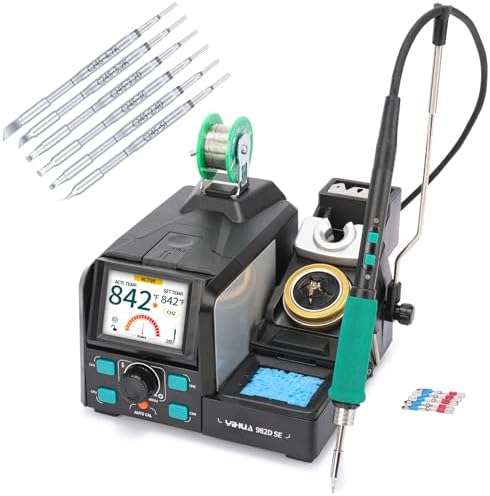
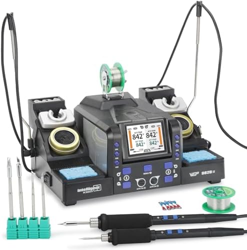
Quick 8620+ Digital Hot Air Soldering Rework Station
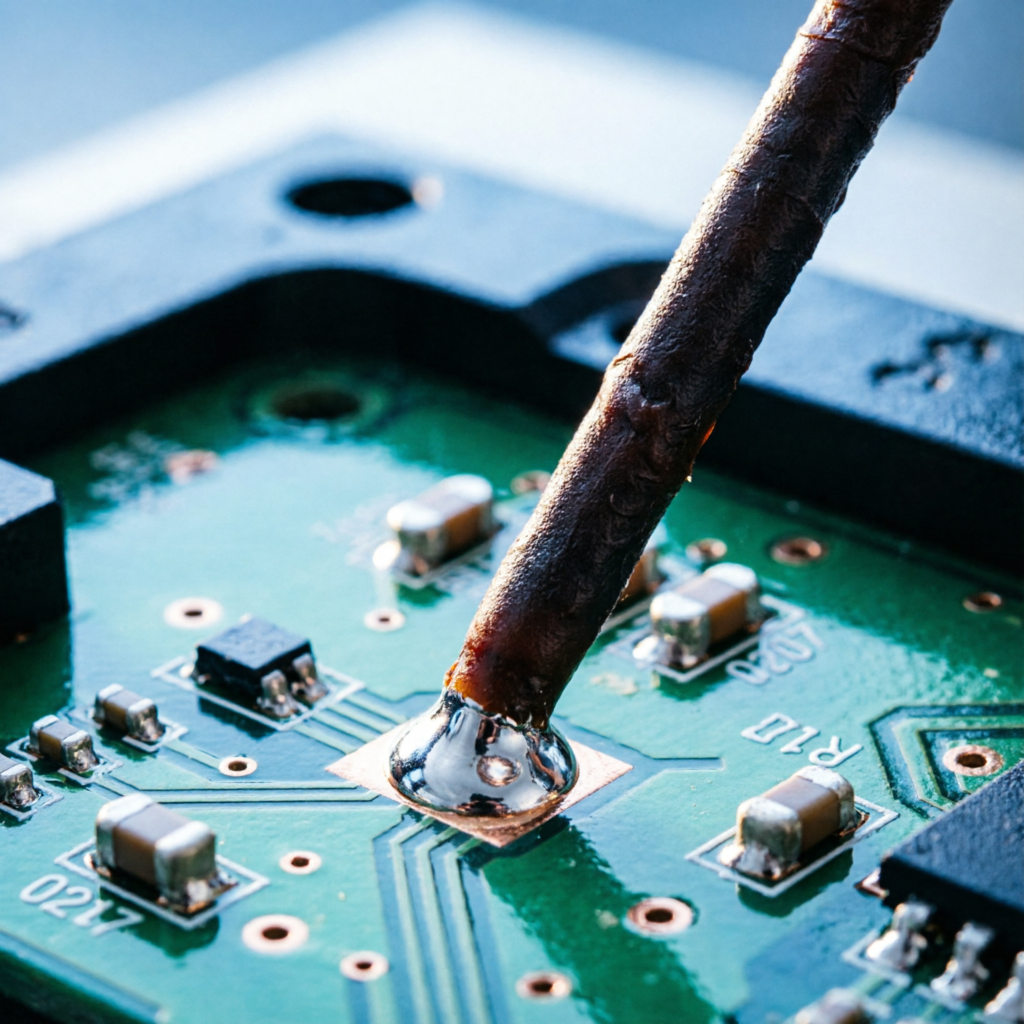
How to Repair Motherboard Copper Trace Using 40 AWG Magnet Wire: The Micro-Soldering Blueprint for High-Ticket Assets
The Technical Reality: Understanding Failure Points
Physical & Environmental Vectors in 4-to-12+ Layer HDI Boards
Modern high-density interconnect (HDI) boards utilize 4 to 12+ layer stacks where critical data and power routing occurs on internal layers.
Mechanical stress from chassis flexing or impact, combined with thermal shock from improper hot-air rework, frequently severs surface copper traces or causes delamination.
Galvanic corrosion further accelerates this degradation in humid environments.
Accessing inner layers to repair these failures requires destructive delamination of the substrate.
Therefore, surface trace repair is mandatory to maintain structural integrity without compromising the board’s multi-layer architecture.
The Physics of Failure: Why 24-30 AWG Destroys Sub-Millimeter SMD Pads
Standard solid or stranded wire in the 24-30 AWG range is physically too thick and rigid for sub-millimeter surface mount device (SMD) pads.
Attempting to bridge a gap with oversized wire creates excessive mechanical leverage on the pad during cooling.
This force leads to pad lifting, thermal damage to the FR4 substrate, and micro-shorts to adjacent high-density pads.
The rigidity prevents the wire from conforming to the microscopic topology of the solder mask, creating stress points that fail under vibration.
Impedance Mismatch & Parasitic Capacitance in High-Speed Data Lines
A poorly executed jumper introduces parasitic capacitance and impedance discontinuities into the signal path.
On high-speed lines such as PCIe Gen 4×4 or 2.5G Ethernet PHY, this mismatch causes signal reflection and packet loss.
Under load, these reflections manifest as complete bus failure.
The physical geometry of the jumper must match the transmission line characteristics to prevent data corruption, which is why standard hookup wire is unacceptable for differential pairs operating above 1 Gbps.
The Core Gear Architecture
Optical Precision: Andonstar AD246S-M (Pro Iteration)
The Andonstar AD246S-M features a 7-inch 2160P LCD with dual-screen HDMI output for zero-latency viewing.
It includes a 30cm+ vertical working clearance bracket, allowing ample space for tool manipulation without obstructing the optical axis.
USB-C Power Delivery (PD) integration supports modern bench setups, while interchangeable A/D/L lenses provide varying focal depths for different component heights.
This eliminates the parallax errors common in lower-end optics.
In-Circuit Diagnostics: FNIRSI LCR-ST1 Smart LCR Tweezers
The FNIRSI LCR-ST1 weighs 41g and houses a 1.14-inch color display powered by a 250mAh Li-ion battery.
It offers selectable test frequencies of 100 Hz, 1 kHz, and 10 kHz, along with dual test voltages of 0.3V and 0.6V.
These parameters allow for precise isolation of components without forward-biasing parallel semiconductor junctions.
This specificity is required to verify continuity on traces shielded by decoupling capacitors.
Check out TECH Collection Amazon Products
| Frequency | Voltage | Application |
|---|---|---|
| 100 Hz | Standard | High-capacity electrolytics |
| 1 kHz | Standard | General resistors and inductors |
| 10 kHz | 0.3V | Low-value ceramic capacitors / Trace impedance verification |
Conductor Material: 40 AWG QA-1 Polyurethane Enameled Magnet Wire
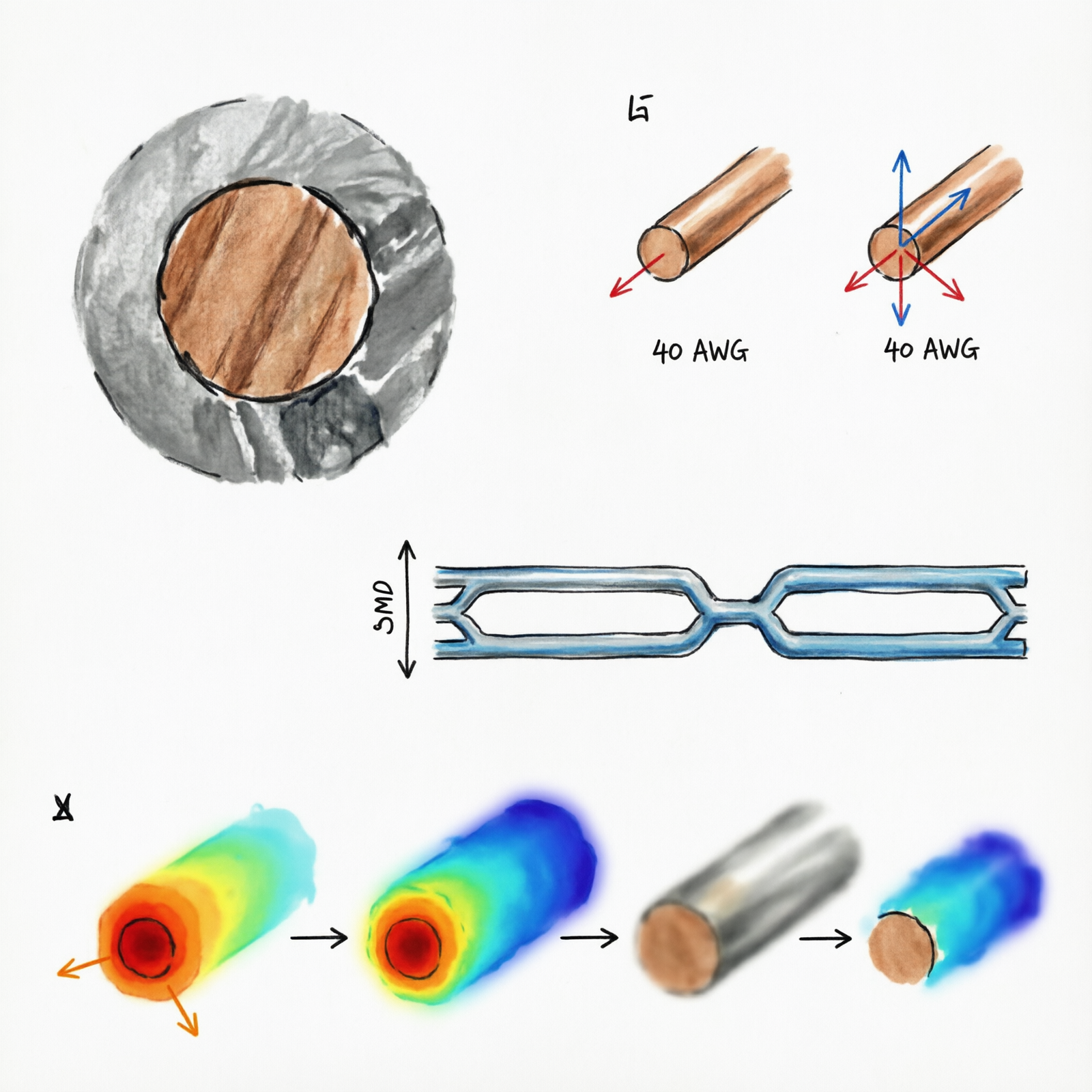
This conductor material has a 0.0799mm bare diameter and a 0.005 mm² cross-sectional area, supporting a max current capacity of approximately 0.15A.
The QA-1 grade self-burning enamel is rated up to 400°C and provides high tensile strength across 100m spools.
The polyurethane enamel acts as an insulator along the wire’s length, preventing short circuits when the jumper crosses over adjacent traces.
This insulation is critical for navigating crowded PCB layouts without bridging connections.
Thermal Control: Quick 8620+ Micro-Rework Station
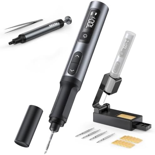
The Quick 8620+ utilizes 0.1mm micro-pencil soldering iron tips capable of reaching 500°C maximum.
It features rapid thermal recovery of less than 2 seconds and digital PID temperature control.
This precision ensures consistent heat delivery to small pads without overheating surrounding components.
The stability of the thermal profile is essential for melting the specific alloy used in modern lead-free solder joints.
2026 Freshness Context: FIPS 140-3 Transition & Next-Gen Pin Density
In September 2026, the CMVP transition moves legacy FIPS 140-2 modules to Historical status.
Replacing failed FIPS 140-3 validated hardware involves massive procurement lead times and costs.
Micro-repair using 40 AWG wire extends the lifecycle of these high-ticket, compliance-critical assets.
Furthermore, modern DDR5/LPDDR5x and Wi-Fi 7 RF traces require extreme precision.
The 2026 optics and smart tweezers are calibrated to handle the increased pin density of these new standards, ensuring repairs meet current regulatory baselines.
The Technical Setup Blueprint
Defeating the “False Continuity” Trap: Forum-Validated Diagnostics
Technicians often encounter the “False Continuity” trap discussed extensively on r/microsoldering and EEVblog.
Standard digital multimeters show continuity (0 ohms) because parallel SMD decoupling capacitors complete the circuit, masking the open trace.
To isolate the specific component or trace, you must use the FNIRSI LCR-ST1 at 10 kHz with 0.3V low-voltage mode.
This frequency targets low-value ceramic capacitors and verifies trace impedance without turning on silicon junctions.
Recommended Insights From Our Guide Library:
- The Ultimate Guide to Motherboard Trace Repair: Creative Fixes for Open Circuits » Z A D A
- Stop Burning Logic Boards: The Precision Trace Repair Protocol for Modern Multi-Layer PCBs » Z A D A
- The Art and Science of Repairing Broken Traces on Printed Circuit Boards (PCBs) » Z A D A
- The Art and Science of Repairing Broken Traces on Printed Circuit Boards (PCBs) » Z A D A
- The Art of Revival: Repairing Liquid-Damaged Electronics at the Component Level » Z A D A
Enamel Burn-Off Protocols: Thermal vs. Mechanical Execution
A common failure point identified in r/AskElectronics is the “visually perfect but electrically dead” joint.
Hobbyists solder 40 AWG wire directly without removing the polyurethane coating.
The solder wets the outside of the enamel, creating infinite resistance despite physical attachment.
The consensus protocol requires either physically scraping with a micro-blade or burning with excess flux and 350°C+ heat before tinning.
This exposes the conductive copper core, ensuring a reliable electrical bond.
Flux Flood Obscuration & Ergonomic Clearances
Using low-quality, high-spatter flux causes the jumper wire to float or become invisible under the microscope.
You must mandate high-viscosity, no-clean tack flux like Amtech or Kingbo to hold the 0.079mm wire in place during tack soldering.
The Andonstar AD246S-M provides critical ergonomic advantages here.
Its 30cm vertical bracket allows 15cm+ of lateral space for hot-air gun nozzles and soldering iron handles.
Dual-screen HDMI maintains ergonomic neck posture and eliminates the 50ms+ latency and parallax errors of cheap USB microscopes that cause torn pads during hand-eye coordination tasks.
Application 1: Fortinet FortiGate 40F / 60F PHY Trace Repair
Target the 5x GE RJ45 ports on the 40F or 10x GE RJ45 ports on the 60F port PHY chips.
These Ethernet PHY traces require 100-ohm differential impedance.
When rebuilding a severed trace to the RJ45 magnetics using 40 AWG wire, the jumper must be kept as short as physically possible, adhering to the <5mm jumper length rule.
If crossing a split plane, twist the jumper with a ground return to minimize impedance mismatch.
This prevents Next-Generation Firewall throughput degradation, maintaining the required 5 Gbps to 10 Gbps performance levels.
Application 2: GEEKOM A9 Max Control/SMBus Recovery
On the GEEKOM A9 Max featuring the AMD Ryzen AI 9 HX 370, 128GB DDR5, and Dual 2.5G LAN, trace repair requires strict categorization.
Explicit Warning: 40 AWG magnet wire is strictly for low-speed control/signal traces such as SMBus, I2C, GPIO, power enable, and reset pins.
Do not use 40 AWG on DDR5 (5600 MT/s+) and PCIe Gen 4×4 (16 GT/s) high-speed data lanes.
Jumpers on these lines introduce fatal parasitic capacitance due to impedance discontinuities.
| Trace Type | 40 AWG Suitability | Risk Factor |
|---|---|---|
| SMBus / I2C / GPIO | Recommended | Low speed, control signals |
| Power Enable / Reset | Recommended | Low current, logic levels |
| DDR5 / PCIe Gen 4×4 | Prohibited | Fatal parasitic capacitance, impedance mismatch |
For high-speed differential pairs, professional BGA reballing or micro-coaxial replacement is mandated.
Correctly repairing control traces ensures network segmentation necessity for Proxmox VE, separating Kubernetes control plane API traffic from worker traffic.
Field Verdict & Operational ROI
Extending the Lifecycle of Compliance-Critical Assets
The 40 AWG micro-repair stack represents a mandatory investment to bypass massive procurement lead times associated with replacing non-compliant or failed FIPS 140-3 validated hardware in the post-2026 CMVP landscape.
By restoring functionality to existing units, organizations avoid the cost and delay of sourcing new FIPS-sealed appliances.
This extends the operational window for security perimeter assets without violating compliance mandates.
Ensuring Physical Layer Stability for SIEM Audit Compliance
Physical trace repair directly impacts cybersecurity outcomes.
A poorly repaired trace causing intermittent packet loss triggers false-positive alerts in Wazuh SIEM logs, specifically flagging SC.L1-3.13.1 continuous monitoring failures.
Precision 40 AWG repair guarantees physical layer stability for audit compliance.
Eliminating these hardware-induced noise floors ensures that security operations centers can trust the integrity of the underlying network infrastructure during audits.
Maintaining Compute Cluster Integrity in DevOps Homelabs
For high-ticket compute nodes, precise trace repair between the CPU and 2.5G RJ45 controllers is non-negotiable.
This ensures the physical separation of Kubernetes control plane API traffic from node-to-node worker traffic in Proxmox VE environments.
Restoring these connections maintains cluster stability and prevents scheduling failures caused by dropped heartbeats.
The ROI lies in preserving the homelab or edge compute environment’s reliability without requiring full hardware replacement.
Conclusion
Repairing motherboard copper traces with 40 AWG magnet wire demands precision, specific tooling, and a deep understanding of signal integrity physics.
By adhering to the 0.0799mm wire specifications, utilizing the FNIRSI LCR-ST1 for accurate diagnostics, and respecting the limitations of high-speed data lanes on platforms like the GEEKOM A9 Max, technicians can restore high-value assets effectively.
Community Reference & Authority Resources:
This approach not only saves significant capital on replacements but ensures continued compliance with evolving standards like FIPS 140-3.
Implementing this blueprint secures your physical layer, stabilizes your SIEM logs, and guarantees the longevity of your critical network infrastructure.
🔍 Explore More: See all tech guides and tutorials for how to repair motherboard copper trace using 40 AWG magnet wire.
Check out TECH Collection Amazon Products