
Hey there, fellow electronics enthusiasts and DIY repair heroes!
Have you ever found yourself staring at a seemingly lifeless circuit board, wondering where to even begin troubleshooting?
It’s a common scenario, and trust me, you’re not alone.
The intricate dance of tiny components on a PCB can be daunting, but identifying a faulty part is often the first and most crucial step in bringing your beloved gadgets back to life.
In this comprehensive guide, we’re going to dive deep into the world of circuit board diagnostics, sharing practical tips, visual cues, and testing methods that will empower you to pinpoint those troublesome components with confidence.
So, grab your multimeter, put on your detective hat, and let’s get started on this exciting journey of electronic repair!
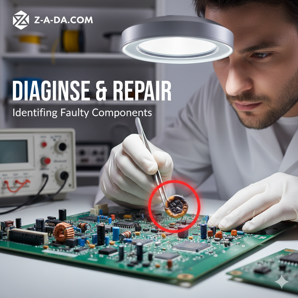
The Art of Visual Inspection: Your First Line of Defense
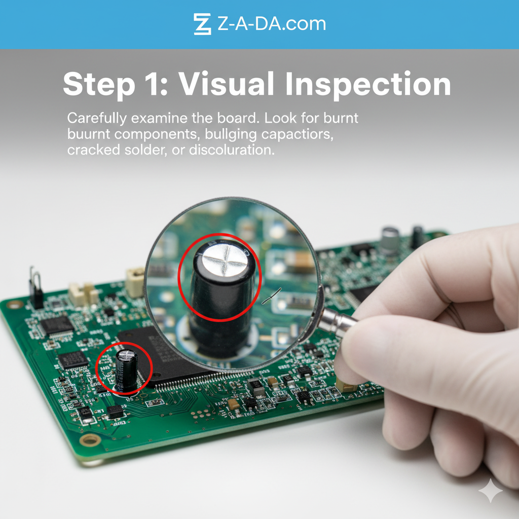
Before you even think about grabbing any tools, the most powerful diagnostic instrument you possess is your own pair of eyes.
A thorough visual inspection can often reveal a wealth of information about a circuit board’s health.
It’s like being a detective, looking for clues that tell a story of what went wrong. What should you be looking for?
First and foremost, keep an eye out for any signs of burn marks or discoloration [1].
These are often tell-tale signs of overheating, indicating that a component has been subjected to excessive current or voltage.
A small brown spot on the PCB or a scorched component can immediately narrow down your search.
Similarly, bulging or leaking capacitors are a classic indicator of failure.
Capacitors, especially electrolytic ones, can swell at the top or bottom when they fail, sometimes even leaking a brownish electrolyte.
If you spot a capacitor that looks like it’s about to burst, you’ve likely found a culprit.
Beyond these obvious signs, pay attention to the overall condition of the board.
Are there any cracked components, lifted traces, or cold solder joints?
Cold solder joints appear dull and grey, rather than shiny and smooth, and can lead to intermittent connections.
Sometimes, components might even be missing or misplaced, especially if the board has been previously worked on or is part of a mass-produced batch with potential manufacturing defects.
Even subtle signs like corrosion or moisture damage can point to environmental factors contributing to the failure [2].
A little bit of rust or a water stain can wreak havoc on delicate electronic pathways.
Remember, a clean, well-lit workspace is your best friend during this stage.
Use a magnifying glass or a jeweler’s loupe if necessary to get a closer look at those tiny surface-mount devices (SMDs). Sometimes, the smallest detail can lead you to the biggest discovery.
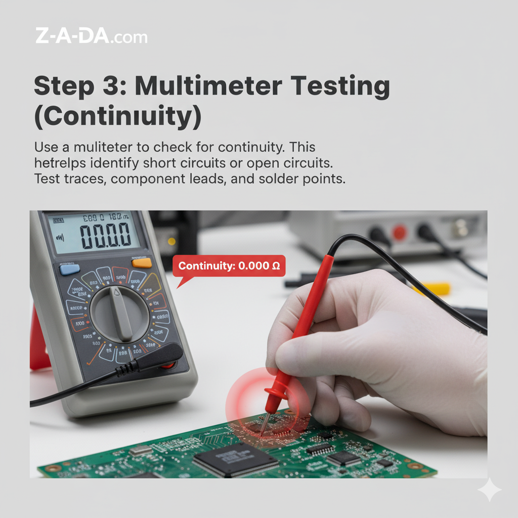
The Multimeter: Your Trusty Sidekick in Troubleshooting
Once your eyes have done their part, it’s time to bring in the heavy artillery: the multimeter.
This versatile tool is indispensable for anyone serious about circuit board repair.
It allows you to measure voltage, current, and resistance, providing concrete data about the electrical behavior of your components.
But how do you use it effectively to find faults?
Before you begin, always remember the golden rule: disconnect power to the circuit[1].
Safety first, always! Once the board is de-energized, you can start testing. A good starting point is to check for short circuits or open circuits.
A short circuit means there’s an unintended path for current, often leading to excessive heat or component failure.
An open circuit means there’s a break in the path, preventing current from flowing where it should.
Your multimeter’s continuity mode is perfect for this.
Touch the probes to two points that should be connected; a beep indicates continuity, while silence suggests an open circuit.
Next, you can start testing individual components.
For resistors, measure their resistance and compare it to the marked value.
Keep in mind that in-circuit measurements can sometimes be misleading due to parallel components, so if you suspect a resistor, it might be best to desolder one leg to test it accurately [1].
For capacitors, especially electrolytic ones, you can check for continuity.
A brief beep followed by a rising resistance indicates the capacitor is charging, which is a good sign.
If it beeps continuously or shows infinite resistance, it might be shorted or open, respectively [1].
Diodes and transistors can also be tested with a multimeter.
Diodes should allow current to flow in one direction (forward bias) and block it in the other (reverse bias).
Your multimeter’s diode test mode will show a voltage drop in forward bias and an open circuit in reverse bias.
Transistors are a bit more complex, but you can test their junctions for proper voltage drops, similar to diodes [1].
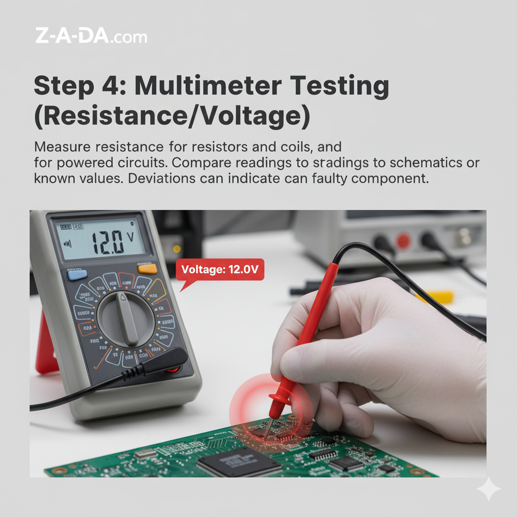
When testing power rails, ensure the board is powered on (with extreme caution, using only one hand to avoid creating a path through your body).
Measure the voltage at various points to ensure they match the expected specifications.
A 0V reading on a power rail often indicates a short circuit, which can cause components to heat up rapidly [1].
Common Component Failures: A Rogues’ Gallery
While any component on a circuit board can fail, some are more prone to issues than others.
Understanding these common culprits can help you narrow down your search and diagnose problems more efficiently.
Let’s take a look at some of the usual suspects:
Capacitors: As mentioned earlier, electrolytic capacitors are notorious for failing.
They have a limited lifespan and are susceptible to drying out, bulging, or leaking, especially when exposed to heat or overvoltage conditions.
When a capacitor fails, it can cause a variety of problems, from a complete loss of power to intermittent issues.
Resistors: While generally reliable, resistors can fail due to overheating or physical damage.
A burnt resistor is easy to spot, but sometimes they can fail without any visible signs.
An out-of-spec resistance value can throw off an entire circuit, so it’s always a good idea to check them with a multimeter.
Diodes and Transistors: These semiconductor devices can be sensitive to electrostatic discharge (ESD) and overvoltage.
A failed diode might become a short circuit, allowing current to flow in both directions, or an open circuit, blocking current entirely.
Transistors can fail in various ways, leading to a loss of amplification or switching capabilities.
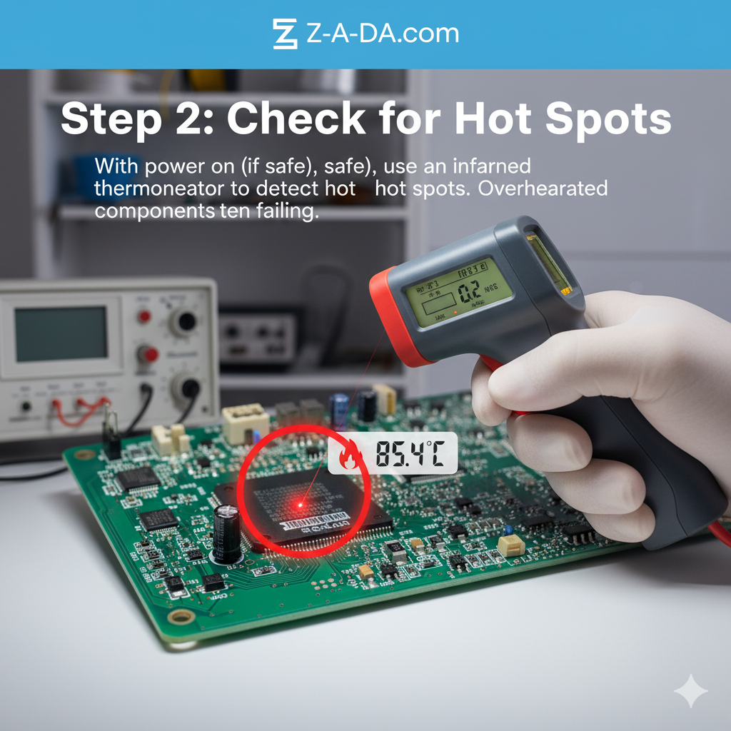
Integrated Circuits (ICs): These complex components can be difficult to diagnose without specialized equipment.
However, they can fail due to overheating, overvoltage, or internal defects.
If you suspect an IC, look for any signs of physical damage, such as cracks or burn marks.
You can also try comparing its temperature to a known good board; an unusually hot IC is a red flag.
Connectors and Solder Joints: It’s not always the components themselves that fail, but the connections between them.
Cold solder joints, cracked solder joints, and corroded connectors can all cause intermittent problems that are frustrating to track down.
A careful visual inspection and a bit of wiggling can often reveal these issues.
By familiarizing yourself with these common failure modes, you’ll be better equipped to identify the root cause of a circuit board problem.
Remember, troubleshooting is a process of elimination, so start with the most likely culprits and work your way through the circuit systematically.
Conclusion: You’ve Got This!
Troubleshooting circuit boards might seem like a black art, but as we’ve seen, it’s a skill that can be learned and honed with practice.
By combining the power of visual inspection with the precision of a multimeter, you can systematically track down and identify faulty components.
Remember to always start with a thorough visual check, looking for the obvious signs of failure like burn marks, bulging capacitors, and physical damage.
Then, with the power disconnected, use your multimeter to test for shorts, opens, and out-of-spec components.
Don’t be discouraged if you don’t find the problem right away.
Electronics repair can be a challenging but incredibly rewarding endeavor.
Each board you work on is a learning experience, and with each successful repair, you’ll build your confidence and skills.
So, the next time you’re faced with a dead gadget, don’t be so quick to throw it away.
Take a deep breath, open it up, and start your investigation.
You might be surprised at what you can fix with a little patience, a few tools, and the knowledge you’ve gained today.
Happy troubleshooting!
References
[1] Cadence. (2024, June 21). *How to Find Faulty Components on a PCB: A Guide . Retrieved from
[2] Wevolver. (2024, March 20). Circuit Board Components Identification: A Comprehensive Guide. Retrieved from