
An unresponsive device, devoid of lights or fans, often signals a logic board power failure.
This central power distribution component’s malfunction is critical.
While daunting, a methodical approach and proper tools enable diagnosis and potential repair.
This guide empowers you to identify, troubleshoot, and fix these issues.
Recognizing the Symptoms: Is It Really a Logic Board Power Issue?
Confirming a power-related logic board problem is key. Common symptoms:
No Power At All: The device is completely dead, with no lights, fan spin, or sounds.
Intermittent Power: The device powers on inconsistently or shuts down unexpectedly.
No Boot/No Display: The device powers on, but the screen remains blank, and it fails to boot.
Burning Smell or Visible Damage: Severe cases may present a burning odor or visible component damage.
A complete lack of device response strongly indicates a power delivery issue from the logic board or its source, differentiating it from other component failures.
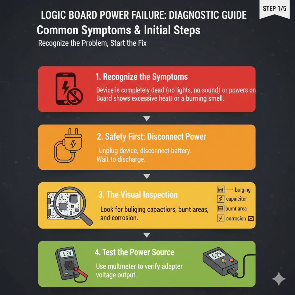
The First Line of Defense: Initial Checks and External Factors
Before opening your device, rule out simple external issues to save time and effort.
Power Supply and Connections
Check your power supply: ensure the cord is secure in the device and a live outlet.
Desktop users, confirm the PSU switch is ‘on’ [ASUS Support].
Loose connections or faulty power strips are common culprits.
Laptop users should try AC power without the battery (if removable) to rule out battery issues.
Don’t overlook these basics!
Peripheral Disconnection
External peripherals can hinder power-on. Disconnect all non-essential devices (USB drives, external hard drives, printers, mouse, keyboard).
If power returns, reconnect them individually to isolate the problematic peripheral. This systematic approach pinpoints the cause.
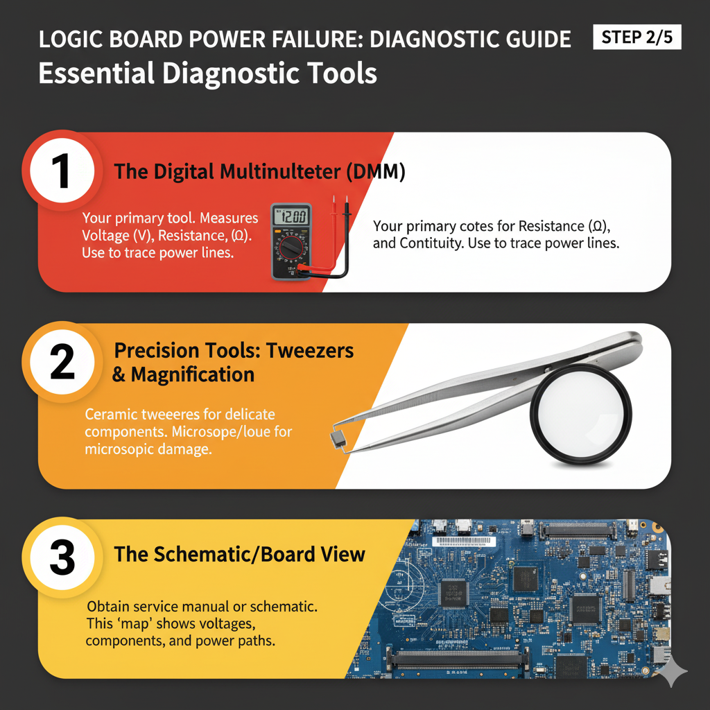
Arming Yourself: Essential Diagnostic Tools
After ruling out external factors, technical diagnosis requires essential tools. The right equipment is crucial.
Multimeter: Your Best Friend
A multimeter is indispensable for electronics troubleshooting, measuring voltage, current, and resistance.
It’s crucial for checking voltage distribution and detecting short circuits [Kaiweets].
Digital multimeters offer accuracy and ease of reading.
Diagnostic Cards (POST Cards)
For desktop motherboards, a Power-On Self-Test (POST) card plugs into a PCI/PCIe slot, displaying boot codes.
These codes indicate failing components or startup stages if the process halts due to power issues [Newegg], narrowing down whether the board receives power but fails to initialize.
Visual Aids: Magnifying Glass and Good Lighting
Never underestimate thorough visual inspection.
A magnifying glass and bright light reveal tiny details:
burnt components, swollen capacitors, or hairline PCB cracks invisible to the naked eye. Simple tools often yield significant discoveries.
The Detective Work: Step-by-Step Troubleshooting
With tools ready, systematically diagnose logic board power failure. This methodical approach covers all bases.
Step 1: Thorough Visual Inspection
Before applying power, conduct a meticulous visual inspection.
Look for swollen or leaking capacitors (common failure point, especially in older boards) [Reddit, EEVblog], burn marks, discoloration, missing/damaged components, corrosion, and loose connections, particularly main ATX power connectors [ASUS Support]. Details matter.
Step 2: Power Supply Unit (PSU) Testing
For desktop PCs, the PSU is a primary suspect.
A simple paperclip test checks basic functionality: disconnect the PSU, then short the green wire (PS_ON) to a black wire (ground) on the 24-pin ATX connector.
A spinning fan indicates partial functionality, but a dedicated tester is needed for full voltage verification. Don’t assume a spinning fan means a healthy PSU.
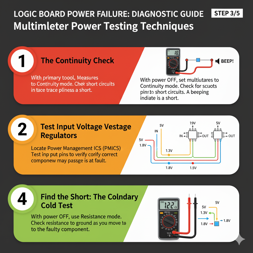
Step 3: Multimeter Magic – Testing Voltages and Shorts
Your multimeter shines here. Before starting, ensure the device is completely disconnected from power. Safety first!
Checking for Short Circuits
Short circuits cause power failure via unintended low-resistance paths. To detect:
1. Continuity Test: Use multimeter’s continuity mode (beep function).
Touch probes to ground points and power rails; a beep indicates a short.
Focus on power input, voltage regulators, and large capacitors [YouTube – How To Find a Short Circuit on a Motherboard Fast].
2. Resistance Measurement: In Ohm mode, measure resistance between power rails and ground.
Very low resistance (near 0 Ohms) suggests a short.
Compare with a known good board if possible.
This comparison is invaluable.
Measuring Voltages
If no shorts and the PSU functions, check logic board voltages with the device powered on (extreme caution).
Precision and care are vital.
1. Main Power Rails: Verify 12V, 5V, and 3.3V rails from the PSU at ATX connectors (consult manual for pinouts).
2. Voltage Regulators (VRMs): These step down voltages for components like CPU, RAM, and chipset.
VRM failure (involving MOSFETs, capacitors, or control ICs) causes incorrect power delivery, leading to no boot or instability.
Diagnose by checking input/output voltages across the module with a multimeter [YouTube – How to Test Voltage Regulators with Multimeter].
3. Standby Power: Confirm 5V standby voltage at ATX connector pins even when off. Its absence indicates a PSU or initial power delivery circuit issue. This small voltage is critical.
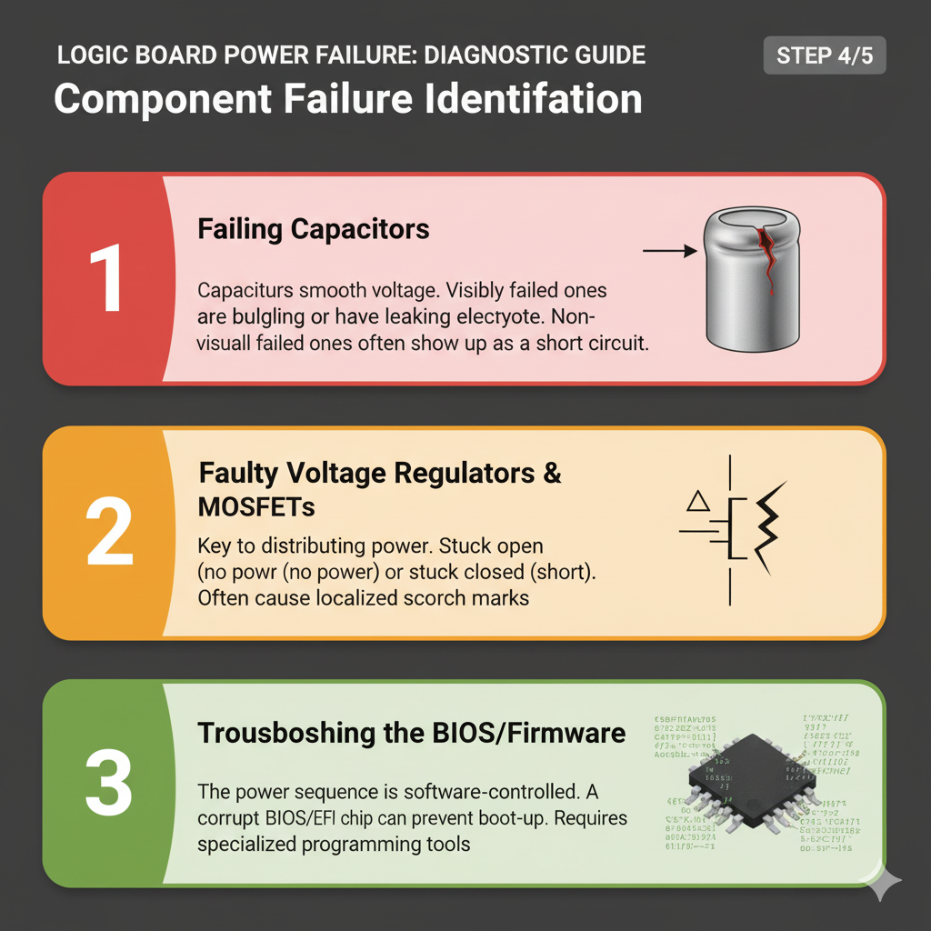
Unmasking the Culprits: Common Failing Components
On complex logic boards, specific components are prone to power failure; knowing these narrows diagnosis.
Here are the usual suspects.
1. Capacitors: The Silent Saboteurs
Electrolytic capacitors are common failure points, especially in older/heat-exposed devices.
They smooth voltage and store energy. Failure leads to unstable power or loss.
Look for bulging, leaking, or bursting; even without visible signs, they can lose capacitance over time, causing intermittent issues
[Reddit – Most common failing components on a PC Motherboard]. Often, they’re the first to fail.
2. MOSFETs (Metal-Oxide-Semiconductor Field-Effect Transistors): The Switching Gates
MOSFETs are electronic switches in VRMs, regulating CPU, GPU, and RAM voltage/current.
Failure can cause short circuits (damaging components) or open circuits (preventing power).
Test for shorts between pins (drain, source, gate) using a multimeter in diode mode. These tiny components are crucial.
3. Diodes: The One-Way Valves
Diodes direct current flow, essential for rectification/protection.
A failed diode can block power or, if shorted, create a power short.
Test with a multimeter in diode mode for forward/reverse bias.
They ensure proper electricity flow.
4. Voltage Regulators (VRMs): The Power Managers
**Voltage Regulator Modules (VRMs)** convert/regulate input voltage to precise levels for components like the CPU.
VRM failure leads to incorrect power delivery, causing no boot/instability.
Diagnose by checking input/output voltages across the module with a multimeter
[YouTube – How to Test Voltage Regulators with Multimeter].
They are stable power’s unsung heroes.
5. Fuses: The Sacrificial Lambs
Fuses protect logic boards from overcurrent.
A blown fuse indicates a short/overcurrent.
These small, surface-mounted components are checked with a multimeter for continuity (no continuity = blown).
Replacing a blown fuse without fixing the underlying short results in immediate re-failure. Always find the root cause!
Beyond the Basics: Advanced Diagnostic Techniques
For stubborn power failures, advanced tools are sometimes necessary.
Thermal Imaging
A thermal imaging camera powerfully diagnoses shorts by pinpointing heat-generating hot spots, saving hours of multimeter probing. It’s like X-ray vision for heat.
Oscilloscope
An oscilloscope visualizes voltage waveforms, diagnosing intermittent power issues, unstable voltages, or switching power supply problems.
It reveals noise, ripple, or incorrect frequencies missed by multimeters, offering deeper insight into power delivery quality and dynamic electrical health.
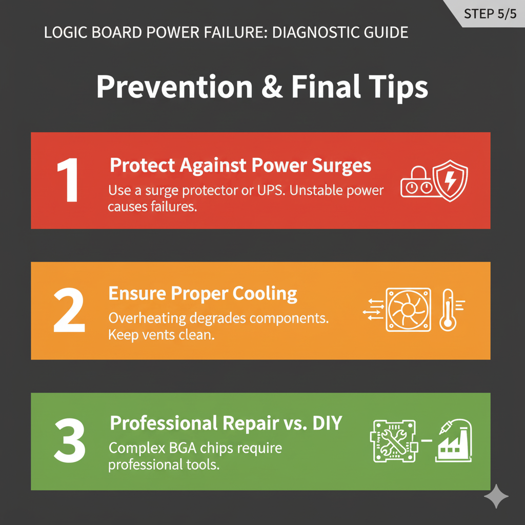
Prevention is Key: Protecting Your Logic Board
Prevention is paramount for logic board power failures; foresight saves headaches.
Surge Protector: A quality surge protector protects devices from damaging power surges.
Proper Ventilation: Prevent overheating (shortens component lifespan) by keeping devices clean and ensuring good airflow; heat is electronics’ enemy.
Handle with Care: Avoid physical damage (drops) causing PCB cracks or dislodged components. Be gentle with your tech!
Quality Power Supplies: Use reliable, high-quality PSUs for stable power delivery, preventing stress/damage to logic board components. Don’t skimp.
Regular Cleaning: Remove dust/debris to prevent insulation, overheating, and conductive shorts. A clean board is a happy board.
Conclusion: Empowering Your Inner Technician
Diagnosing logic board power failure is daunting, but a systematic approach, understanding common failure points, and using the right tools builds confidence.
External checks, multimeter probing, and thermal imaging identify the root cause.
Patience and methodical troubleshooting are key to reviving devices. Happy troubleshooting!
References
* [ASUS Support] ASUS. (n.d.). [Motherboard] Troubleshooting – No Power/No Boot/No Display. Retrieved from
* [Kaiweets] Kaiweets. (2022, September 23). How to Test a Motherboard with a Multimeter*l. Retrieved from
* [Newegg] Newegg. (n.d.). *motherboard tester*. Retrieved from
* [Reddit] Reddit. (2022, February 15). *Most common failing components on a PC Motherboard*. Retrieved from
* [EEVblog] EEVblog. (2022, September 28). *Common failing parts on old(er) circuit boards*. Retrieved from
[YouTube – Short Circuit] Learn Electronics Repair.
(2024, June 14). The Fastest Way To Detect Short Circuit On Motherboards. Retrieved from
[YouTube – Voltage Regulators] Learn Electronics Repair. (n.d.). How to Test Voltage Regulators with Multimeter – LD1117. Retrieved from