
Diagnosing the Burn: Finding the Root Cause of Overheating on a Circuit Board
A scorching hot circuit board (PCB) is more than just a warning sign; it’s a guaranteed path to system failure and component degradation. 💥
In the world of modern electronics, where devices are smaller, faster, and more powerful than ever, thermal management has become the single most critical challenge. 🔥
The imperative isn’t just about cooling the board; it’s about finding and fixing the root cause of the excessive heat generation. 🔍
This is the difference between a temporary fix and a reliable, long-term solution. ✅
This post delves into the latest data and techniques for diagnosing, locating, and resolving the common, and sometimes unexpected, causes of overheating on a circuit board. 🛠️
The Overheating Imperative: Why Heat Kills Electronics 💀
Heat is the enemy of semiconductors. 💔
Every 10°C increase in a component’s operating temperature can effectively halve its lifespan, according to general reliability standards like the Arrhenius model. 📉
High temperatures lead to irreversible physical changes: 👇
- Thermal Runaway: Certain components, like transistors, get hotter as they pass more current, which, in turn, makes them pass even more current, creating a destructive feedback loop. 🌀
- Solder Joint Fatigue: Constant heating and cooling cycles cause the PCB substrate and solder joints to expand and contract at different rates, leading to micro-cracks and eventual failure. 💔
- Capacitor Degradation: Electrolytic capacitors dry out faster, losing capacitance and increasing equivalent series resistance (ESR). 🧪
Understanding this fundamental relationship confirms that finding the cause of overheating is an essential diagnostic step, not just an aesthetic one. 📌
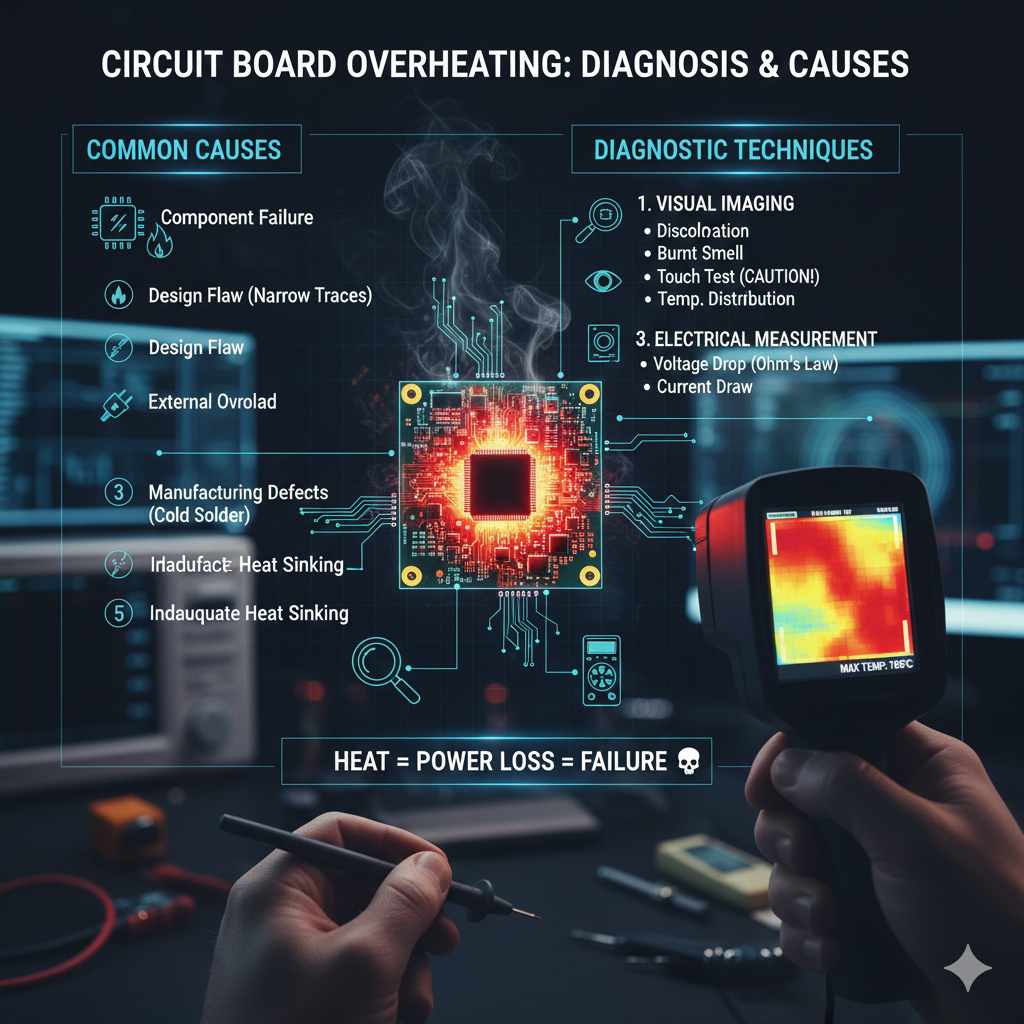
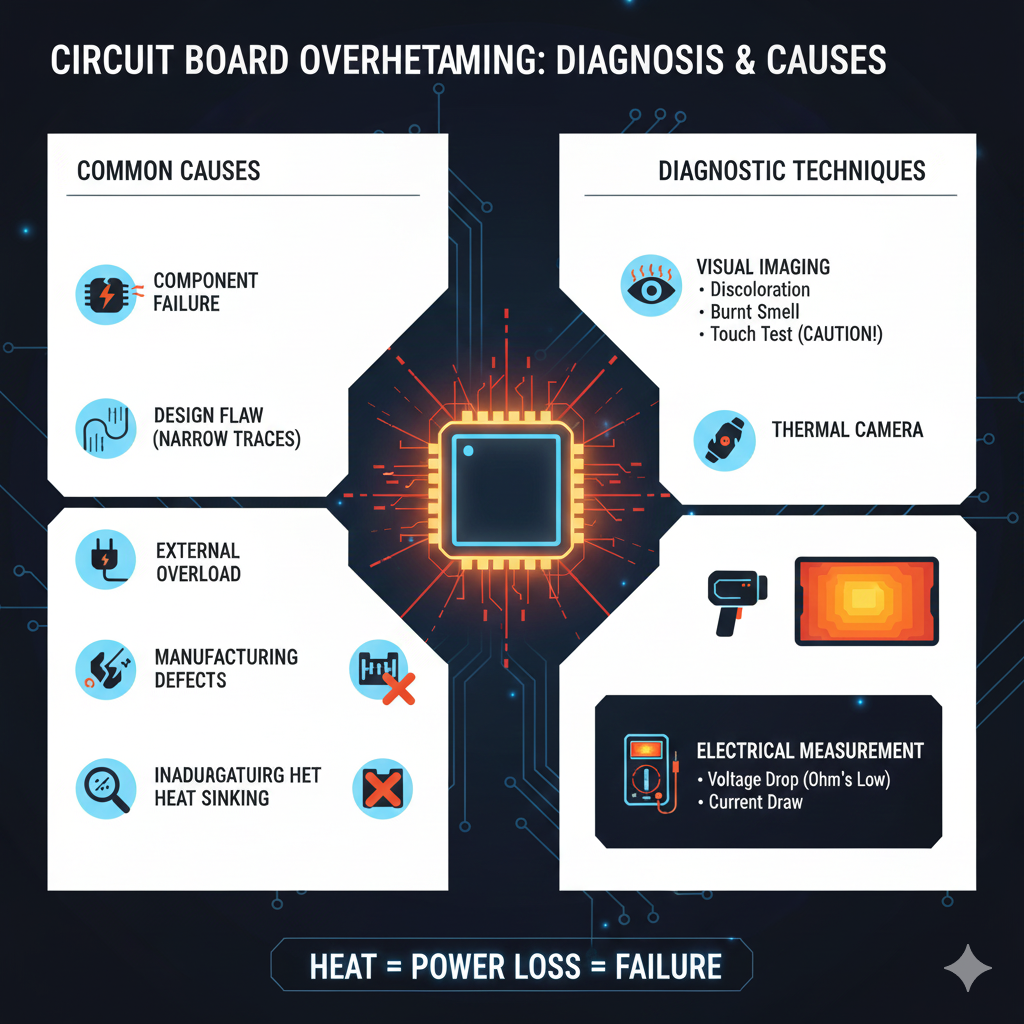
Phase 1: Diagnostic Tools and Techniques 🔬
You can’t fix what you can’t see. Since heat is invisible, specialized tools are necessary to pinpoint its source. 🧐
Thermal Imaging and Cameras 🌡️
The single most valuable tool for troubleshooting PCB heating is a thermal camera.
This device instantly provides a heat map, allowing technicians to see exactly which component is running hottest. 🔴
The latest cameras offer high thermal sensitivity (<0.03^{\circ}\text{C} resolution), allowing for the detection of subtle temperature differences. 📈
You should capture images of the board both at startup and under full load conditions. 📸
“A problem well stated is a problem half solved.” – Charles Kettering
Probe and Measurement Techniques 📏
Once a hotspot is identified with the camera, quantitative measurement is needed: 🎯
- Digital Multimeter (DMM): Use a DMM to measure voltage drop across copper traces or current draw into a specific section of the board. An abnormally high current draw confirms the component is the culprit. ⚡
- Ohm’s Law Application: Calculate the power dissipation (P) using the measured current (I) and voltage drop (V) or resistance (R). P = V \times I or P = I^2 \times R. Excessive power dissipation is the overheating. 💡
- Logic Analyzer / Oscilloscope: If the overheating occurs only during specific operational states (e.g., data transfer), these tools help correlate heat spikes with specific electronic events. 📊
Phase 2: Common Root Causes of Overheating culprits 🕵️♂️
Heat on a PCB almost always stems from power dissipation. This power is lost due to resistance or impedance within the circuit. 🔌
The causes can be broadly categorized: 👇
| Category | Specific Cause |
|---|---|
| Component Failure | A component (IC, MOSFET, Regulator) is partially shorted, drawing excessive current and dissipating it as heat. |
| Design Flaw | Trace widths are too narrow for the current load, causing high current density and resistive heating in the copper itself. |
| External Load | The device connected to the PCB (e.g., a motor, LED array) draws more power than anticipated or shorts out, overloading the power supply components. |
| Manufacturing Defect | Poorly soldered joints, cold joints, or manufacturing voids/scratches in traces increase localized resistance. |
| Inadequate Heat Sink | The component is operating correctly, but the designed thermal path (heat sink, thermal vias, copper planes) is insufficient to move the heat away. |
Specific Component Culprits 🌋
While any component can fail, some are naturally higher power dissipators and should be checked first: 🔎
- Voltage Regulators (LDOs and Switching Regulators): Linear Regulators (LDOs) are notorious for converting excess voltage into heat (P_{loss} = (V_{in} – V_{out}) \times I_{out}). If the regulator is the hotspot, check the input voltage and load current. 🛑
- Power MOSFETs: These are common in motor drivers and switching power supplies. Overheating often means the gate driver signal is poor (slow switching speed) or the MOSFET is partially damaged (high R_{DS(on)}). 💡
- High-Speed Processors/FPGAs: These components dissipate immense power. If they are overheating, the issue is often related to inadequate heat sinking or software/firmware running inefficient operations, causing high core utilization. 💻
“You can’t solve a problem on the same level that it was created. You have to rise above it to the next level.” – Albert Einstein
Phase 3: Advanced Diagnostic Deep Dive 🌊
When the component itself isn’t clearly at fault, the issue is usually hidden in the PCB layout or power delivery network (PDN). 💡
Investigating Poor Design and Layout 📏
Design tools offer sophisticated simulation, but real-world conditions can expose flaws: 🔬
Focus on Trace Resistance: The resistance of a copper trace (R) is given by R = \rho \frac{L}{A}, where \rho is copper resistivity, L is length, and A is the cross-sectional area (width \times thickness). 📐
If a high-current trace is visibly hot, it is almost certainly too narrow. Current density in the trace is too high, converting energy into heat. 🥵
High current density is especially dangerous near component pins and barrel connectors, where the copper neck-down is most likely. 🤏
Check Vias: Vias connecting power planes between layers can act as thermal choke points. If a plane is supposed to be carrying heat away, ensure there are sufficient thermal vias (heat pipes) to the next layer. 🔗
Inadequate return paths (ground loops) can also force current to take longer, more resistive routes, generating heat across unintended areas. 🛣️
External Links for Deeper Understanding 📚
To further refine your diagnostic skills, consult these expert resources: 👇
- EE Times on Thermal Management Techniques for PCBs – Detailed look at design principles to avoid excessive heat. 📈
- Texas Instruments Application Note on PCB Thermal Design – Focuses on best practices for power components like LDOs and MOSFETs. 📖
- IPC Standards for Electronic Design – Reference industry standards for current carrying capacity in PCB traces. 🏭
- FLIR Guide to Thermal Analysis of PCBs – Practical guidance on using thermal imaging for electronic diagnostics. 🌡️
- Analog Devices on Current Density and PCB Vias – Technical article explaining how poor via placement leads to heat. 🔗
The Repair and Prevention Mindset 🛠️
Once the cause is found, the solution is often a redesign. However, quick fixes can include: 🏃♀️
- Adding Local Heat Sinks: Attaching a dedicated heat sink to the specific overheating component using thermal paste or adhesive. ❄️
- External Cooling: Increasing airflow with a fan or improving the enclosure’s ventilation. 💨
- Component Swap: Replacing a linear regulator (LDO) with a more efficient switching regulator (DC-DC converter) to reduce power loss (P). 🔄
The ultimate goal, however, is prevention. Use thermal simulation tools (FEA) during the design phase to predict hotspots before the first prototype is manufactured. 💻
Conclusion 🎉
Overheating on a circuit board is a complex issue, often stemming from a hidden confluence of component failure, poor layout choices, or insufficient thermal paths. 🧐
By leveraging modern diagnostic tools like thermal cameras and applying a methodical, power-focused approach, engineers and technicians can move beyond simple cooling and truly find the root cause. 🎯
This dedication to thermal integrity ensures not only the immediate function of an electronic device but its long-term reliability and success. 🌟
Diagnose the burn to prevent the breakdown! 🛑
Ready to apply these diagnostic techniques to your next project? Ensuring thermal integrity is the foundation of reliable electronics. 🚀